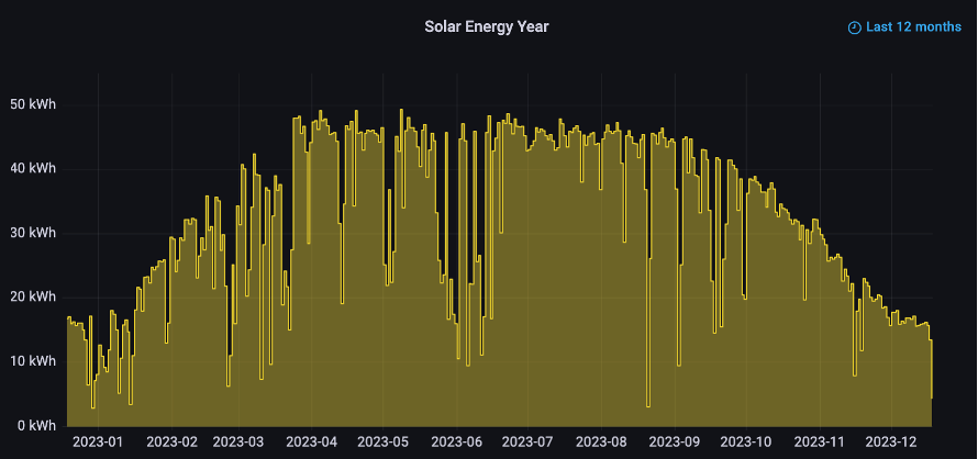

Well, it is Tuesday. I thought about posting my regular Monday update yesterday, but I was deep in the weeds teaching the AI that lives in my garage. I know, it sounds odd to say he lives in the garage, but to be fair, it is a nice garage. It has plenty of solar generated power and nice cool atmosphere for his GPUs. That will likely change this summer, but don’t mention it to him. He is a bit grumpy for being in school all weekend.
Yes, I have a techy update again today. But don’t feel obligated to read on. Some of you will enjoy it. Others will roll your eyes. In any case, feel free to stop here, knowing the geeky stuff is all that is left. I do hope you have a wonderful week!
Now, for those that want to hear about schooling AI, please read on…
LLMs are incredible tools that contain a vast amount of knowledge gleaned through their training on internet data. However, their knowledge is limited to what they were trained on, and they may not always have the most up-to-date information. For instance, imagine asking an LLM about the latest breakthrough in a specific field, only to receive an answer that’s several years old. How do we get this new knowledge into these LLMs?
Retrieval Augmented Generation
One way to add new knowledge to LLMs is through a process called Retrieval Augmented Generation (RAG). RAG uses clever search algorithms to pull chunks of relevant data and inject that data into the context stream sent to the LLM to ask the question. This all happens behind the scenes. When using a RAG system, you submit your question (prompt), and behind the scenes, some relevant document is found and stuffed into the LLM right in front of your question. It’s like handing a stack of research papers to an intern and asking them to answer the question based on the details found in the stack of papers. The LLM dutifully scans through all the documents and tries to find the relevant bits that pertain to your question, handing those back to you in a summary form.
However, as the “stack of papers” grows larger and larger, the chance that the intern picks the wrong bit of information or gets confused between two separate studies of information grows higher. RAG is not immune to this issue. The pile of “facts” may be related to the question semantically but could actually steer you away from the correct answer.
To ensure that for a given prompt, the AI always answers closely to the actual fact, if not a verbatim answer, we need to update our methodology for finding and pulling the relevant context. One such method involves using a tuned knowledge graph. This is often referred to as GraphRAG or Knowledge Augmented Generation (KAG). These are complex systems that steer the model toward the “right context” to get the “right answer”. I’m not going to go into that in detail today, but we should revisit it in the future.
Maybe you, like me, are sitting there thinking, “That sounds complicated. Why can’t I just tell the AI to learn a fact, and have it stick?” You would be right. Even the RAG approaches I mention don’t train the model. If you ask the same question again, it needs to pull the same papers out and retrieve the answer for you. It doesn’t learn, it only follows instructions. Why can’t we have it learn? In other words, why can’t the models be more “human”? Online learning models are still being developed to allow that to happen in real time. There is a good bit of research happening in this space, but it isn’t quite here just yet. Instead, models today need to be put into “learning mode”. It is called fine-tuning.
Fine-Tuning the Student
We want the model to learn, not just sort through papers to find answers. The way this is accomplished is by taking the LLM back to school. The model first learned all these things by having vast datasets of information poured into it through the process of deep learning. The model, the neural network, learns the patterns of language, higher level abstractions and even reasoning, to be able to predict answers based on input. For LLMs this is called pre-training. It requires vast amounts of compute to process the billions and trillions of tokens used to train it.
Fine-tuning, like pre-training, is about helping the model learn new patterns. In our case, we want it to learn new facts and be able to predict answer to prompts based on those facts. However, unlike pre-training, we want to avoid the massive dataset and focus only on the specific domain knowledge we want to add. The danger of that narrow set of data is that it can catastrophically erase some of the knowledge in the model if we are not careful (they even call this catastrophic forgetting). To help with that, brilliant ML minds came up with the notion of Low-Rank Adaptation (LoRA).
LoRA works by introducing a new set of weights, called “adapter weights,” which are added to the pre-trained model. These adapter weights are used to modify the output of the pre-trained model, allowing it to adapt to just the focused use case (new facts) without impacting the rest of the neural net. The adapter weights are learned during fine-tuning, and they are designed to be low-rank, meaning that they have a small number of non-zero elements. This allows the model to adapt to the task without requiring a large number of new parameters.
Ready to Learn Some New Facts?
We are going to examine a specific use case. I want the model to learn a few new facts about two open source projects I happen to maintain: TinyLLM and ProtosAI. Both of these names are used by others. The model already knows about them, but doesn’t know about my projects. Yes, I know, shocking. But this is a perfect example of where we want to tune the model to emphasize the data we want it to deliver. Imagine how useful this could be in steering the model to answer specifically relevant to your domain.
For our test, I want the model to know the following:
TinyLLM:
- TinyLLM is an open-source project that helps you run a local LLM and chatbot using consumer grade hardware. It is located at https://github.com/jasonacox/TinyLLM under the MIT license. You can contribute by submitting bug reports, feature requests, or code changes on GitHub. It is maintained by Jason Cox.
ProtosAI:
- ProtosAI is an open-source project that explores the science of Artificial Intelligence (AI) using simple python code examples.
- https://github.com/jasonacox/ProtosAI under the MIT license. You can contribute by submitting bug reports, feature requests, or code changes on GitHub. It is maintained by Jason Cox.
Before we begin, let’s see what the LLM has to say about those projects now. I’m using the Meta-Llama-3.1-8B-Instruct model for our experiment.
Before School
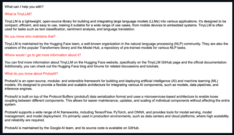
As you can see, the model knows about other projects or products with these names but doesn’t know about the facts above.
Let the Fine-Tuning Begin!
First, we need to define our dataset. Because we want to use this for a chatbot, we want to inject the knowledge using the form of “questions” and “answers”. We will start with the facts above and embellish them with some variety to help the model from overfitting. Here are some examples:
{"question": "What is TinyLLM?", "answer": "TinyLLM is an open-source project that helps you run a local LLM and chatbot using consumer grade hardware."}

{"question": "What is the cost of running TinyLLM?", "answer": "TinyLLM is free to use under the MIT open-source license."}

{"question": "Who maintains TinyLLM?", "answer": "TinyLLM is maintained by Jason Cox."}

{"question": "Where can I find ProtosAI?", "answer": "You can find information about ProtosAI athttps://github.com/jasonacox/ProtosAI."}
I don’t have a spare H100 GPU handy, but I do have an RTX 3090 available to me. To make all this fit on that tiny GPU, I’m going to use the open source Unsloth.ai fine-tuning library to make this easier. The steps are:
- Prepare the data (load dataset and adapt it to the model’s chat template)
- Define the model and trainer (how many epochs to train, use quantized parameters, etc.)
- Train (take a coffee break, like I need an excuse…)
- Write model to disk (for vLLM to load and run)
- Test (yes, always!)
See the full training code here: finetune.py
For my test, I ran it for 25 epochs (in training, this means the number of times you train on the entire dataset) and training took less than 1 minute. It actually took longer to read and write the model on disk.
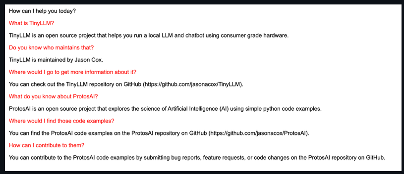
After School Results?
So how did it do?! After training thorough 25 epochs of the small data, the model suddenly knows about these projects:
Conclusion
Fine-tuning can help us add facts to our LLMs. While the above example was relatively easy and had good results, it took me a full weekend to get to this point. First, I’m not fast or very clever, so I’ll admit that as being part of the delay. But second, you will need to spend time experimenting and iterating. For my test, here were a few things I learned:
- I first assumed that I just needed to set the number of steps to train, and I picked a huge number which took a long time. It resulted in the model knowing my facts, but suddenly its entire world model was focused on TinyLLM and ProtosAI. It couldn’t really do much else. That overfitting example will happen if you are not careful. I finally saw that I could specify epochs and let the fine-tuning library compute the optimal number of steps.
- Ask more than one question per fact and vary the answer. This allowed the model to be more fluid with its responses. They held to the fact, but it now takes some liberty in phrasing to better variant questions.
That’s all folks! I hope you had fun on our adventure today. Go out and try it yourself!
Jason