The Order
25 June 2021
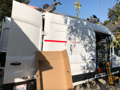
After research and talking with several solar companies, we decided on an 8.5kW Tesla Solar plus Powerwall+ system with their new high efficiency 425W panels. The main reason for our decision was the low cost, handsomely framed panels and the whole house backup capability. Other solar companies had good backups systems but we did not find any who would provide whole house backup. And, more importantly, we were delightfully surprised to see that Tesla came in with the best price. Having said that, we would soon discover that they seemed to have significantly reduced overhead by mostly eliminating customer service.
The Install
25 September 2021
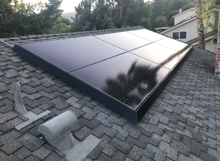
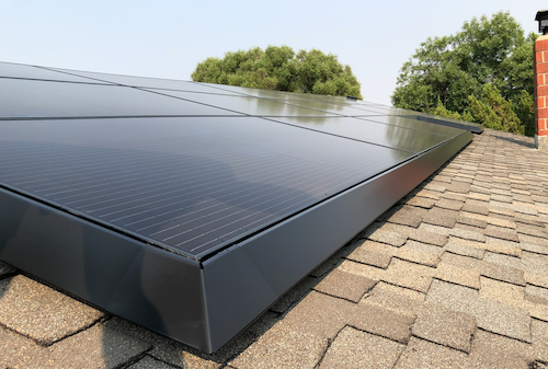
After ordering, reviewing designs, applying for HOA and City approval, we were finally ready to get the system installed. Two different crews arrived over a span of a week to get the system installed. The panels went on first. The panel install crew was professional and friendly. However, when they left I noticed that the handsome skirts (frames) we were so excited about were only installed on the front of the house (street facing roof). It looked great but I had expected to get them on the back as well. I reported it and in just a few days a technician came out and added the skirts to the back roof panels. He explained that they usually only install the skirts on the front. So, please note, if you want skirts on all your panels, make sure you let them know in advance. Also, the skirts are only put on the left, right and bottom. There are no skirts on the top to allow heat to escape from the panels during the hot summer.
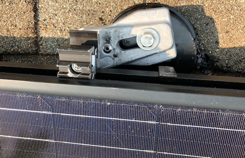
While installing the skirts for the back, I noticed one of the panel edges was sticking up about 1/2″ higher than the rest. The technician tried to fix it but he didn’t have all the tools. He only had what was needed to install the skirts. He asked me if I had a Torx T30 driver. I didn’t but he explained how I could adjust the panels myself. I picked up a T30 at our Newhall True Value store. I climbed up on the roof and found the adjustment area. I used a vice grip on the screwdriver to get enough leverage (mostly because I’m pretty weak especially when I’m up on the roof). I was able to lower the panel 1/2″ so it was flush. It looked beautiful.
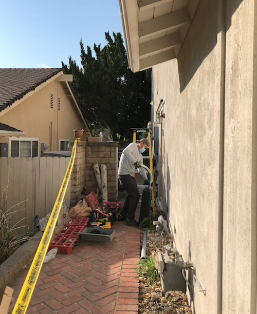
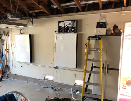
A week later, another crew showed up to wire it in and commission the system. This meant a day without power, but we were prepared for that. I tried not to be a nuisance, but couldn’t help but watch and ask questions. I made sure all of the crew had plenty of bottled water, Gatorade and snacks, including ice cream candy bars since it was so hot. They installed the Powerwalls in our garage and wired in the breaker panels and Tesla Gateway by the utility meter. After everything was installed, they powered it up and began the commissioning process.
The Problem
During commissioning, the first signs of trouble started showing up. The installers downloaded the latest software updates but were unable to get the Solar Panels to work correctly. The solar assembly was only producing 160W in full sun which doesn’t even show up in the app. They tried for hours, upgrading, rebooting, calling. They eventually gave up after showing me that the Powerwall could power our house if they cut the mains (based on 22% charge from the factory). They explained that Tesla would send out a software patch to fix the Solar panels, most likely.
I contacted our Tesla Advisor to report the problem and to see if they had an update. After several days of emailing, texting and calling, I received a note from the advisor that our inspection would be scheduled in 3-4 weeks and he would contact the electrician about the problem. I spent another week requesting updates but my Advisor had gone radio silent. It turns out that this is a common experience with Tesla. Assuming best intentions, I can only imagine that the advisors are understaffed and overwhelmed. Regardless, it all results in a very frustrating experience for the customer.
I did manage to finally get an update and a promise to further investigate the issue. While I waited, I decided to do some more research on the system to see if I could find the problem myself…
HIGH VOLTAGE WARNING: I need to stop here and remind everyone that these systems contain extremely high voltages and are dangerous. Hopefully it goes without saying, but please be careful if you poke around inside these electrical boxes. High voltage can be fatal.
The Investigation
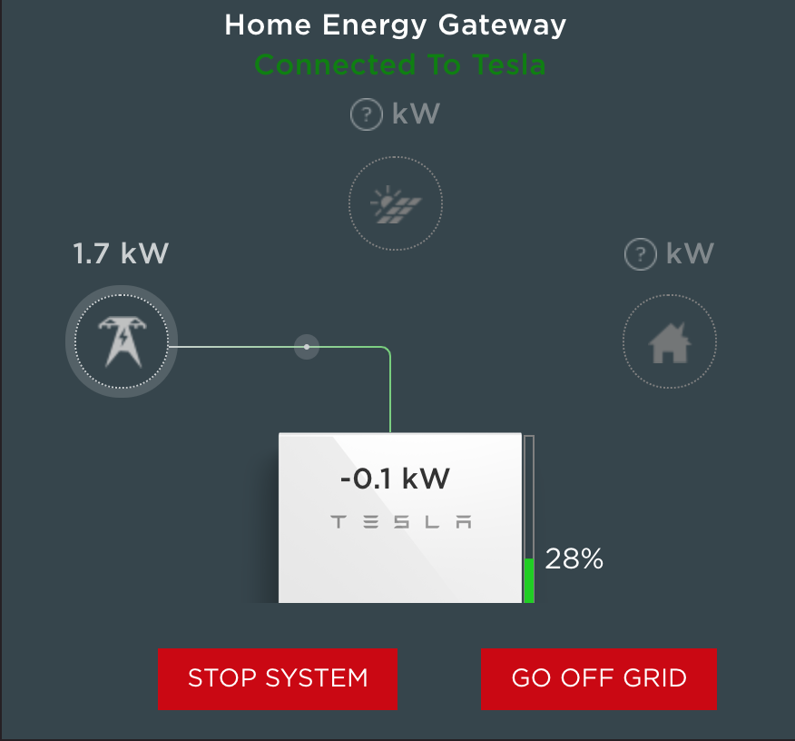
You can connect to the Tesla Gateway by scanning the QR code inside the box. It will have your phone connect to the Gateway’s access point. You will need to stay close to the gateway if you connect this way (and browse to https://192.168.91.1). However, keep in mind that it is also connected to your home network and if you know how to find the IP address, you can point your browser to that IP and login as the Installer to see more details about the system. Your browser will likely require that you ignore the security certificate warning (more on this in the observations section below) and you will need to toggle the power switch to one of your Powerwalls but it will let you in. That is essentially their 2nd factor system to ensure you are authorized. Here is what my system looked like after installation on the main screen and on the “System” screen :
The System screen also shows details about the solar generation, Powerwalls and power usage:
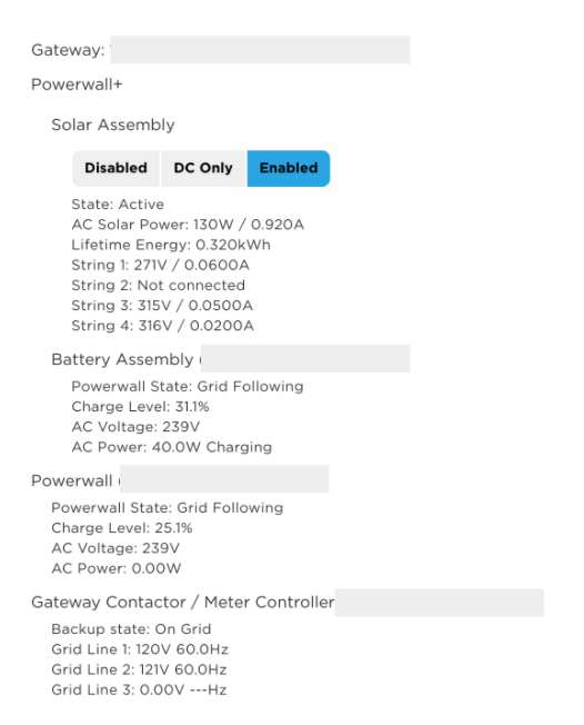
Below the above list was a section for “Remote Meter” that would occasionally appear. This was particularly interesting:
Remote Meter (Vxxxxxxxxxxxxxxx)
CT 1 (Solar): —W
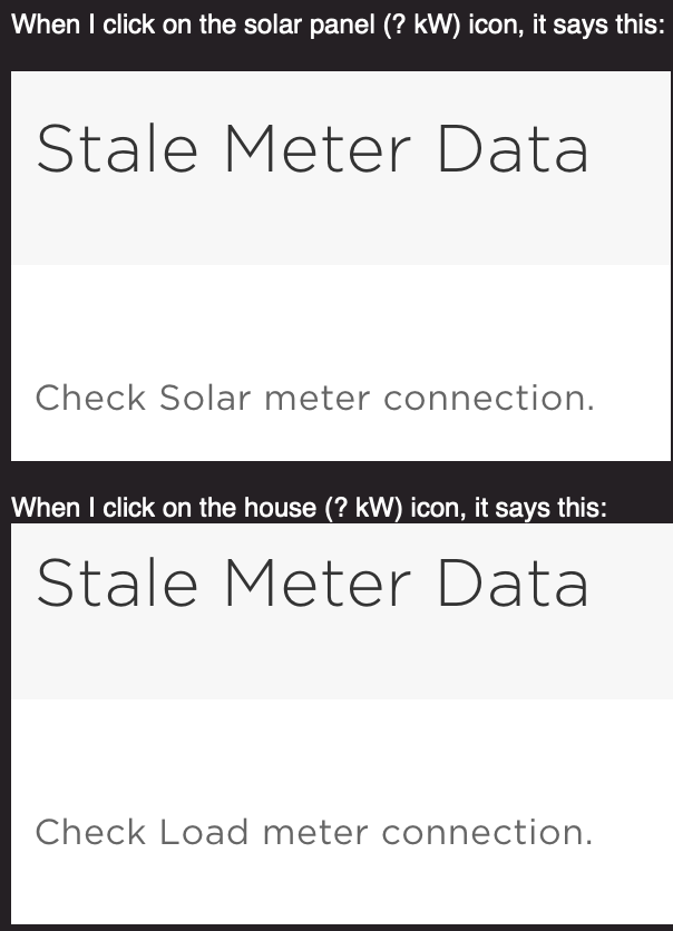
That seemed odd. Also when I clicked on the solar panel icon on the main screen, it would say “Stale Meter Data” – that had me wondering if the solar meter was the real issue.
The Fix?
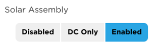
I first disabled the Solar Assembly by clicking “Disable” on the System screen.
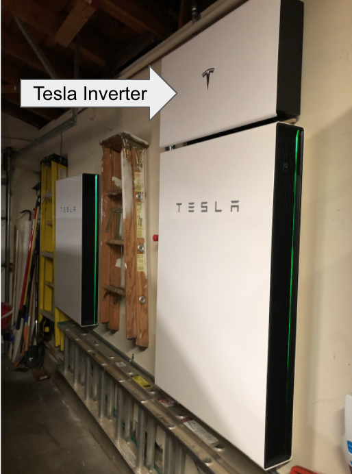
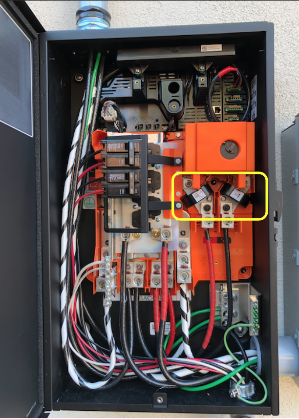
I opened up the Inverter, the box above the first Powerall. There is a small latch on the bottom that will unlock and let the panel swing up. I found a wooden dowel to prop it open so it would bang on my head the whole time I was investigating.
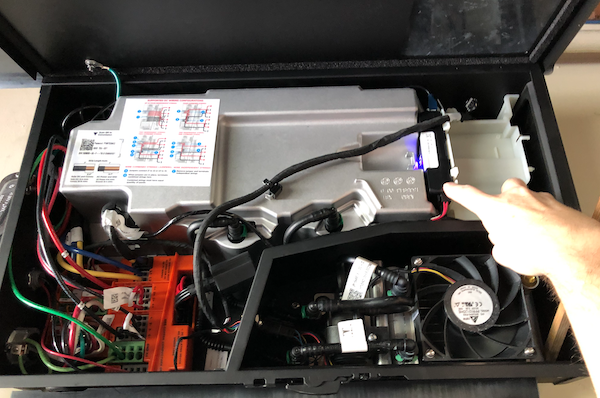
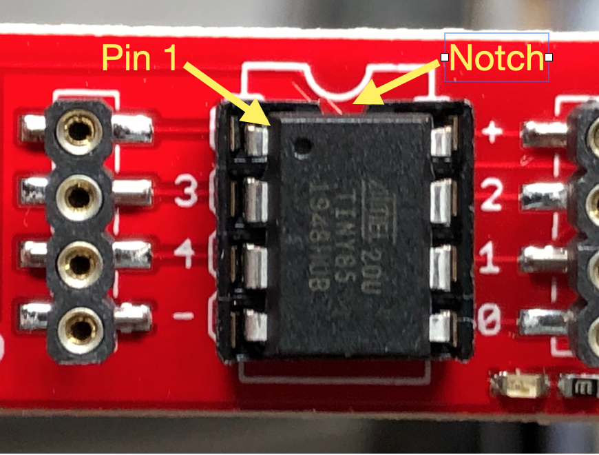
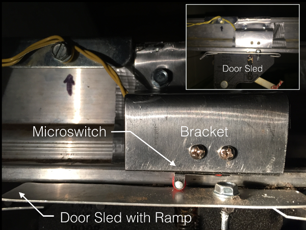
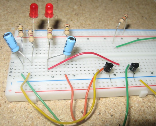
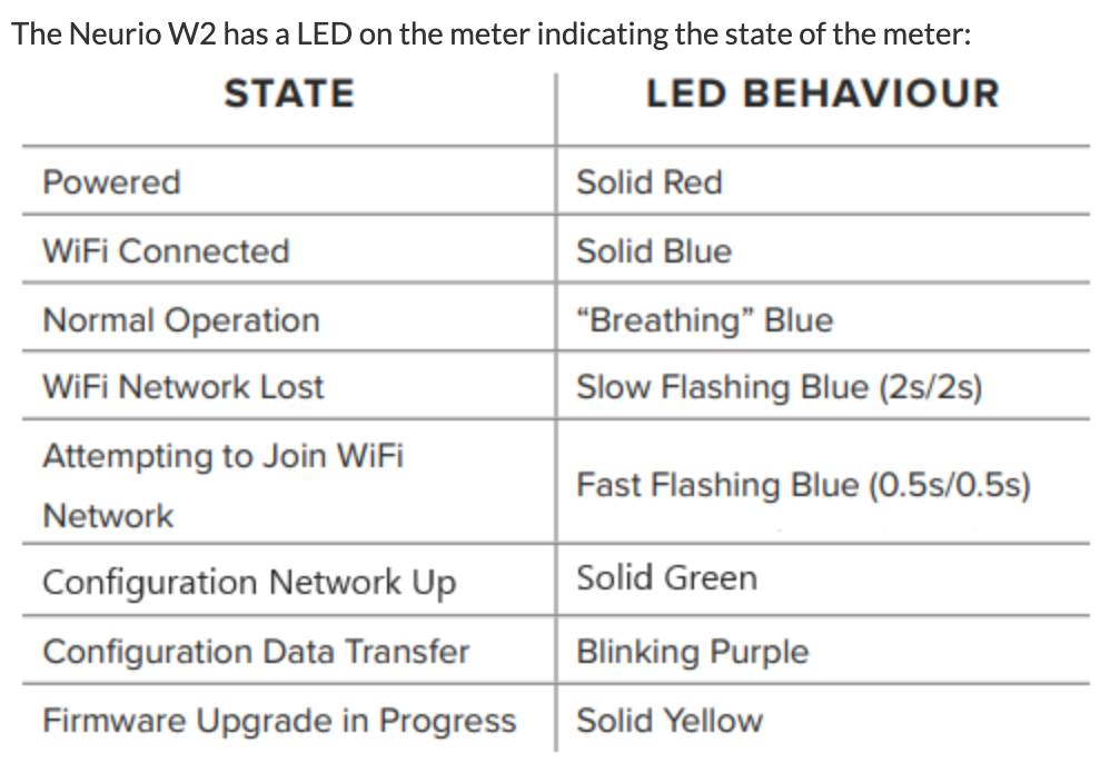
I noticed that there was a box on the right that had a “n” LED flashing. The code on the box was the same code that was listed as the “Remote meter” in the system’s display (the one showing no power). Some more research and I discovered that this module is a Neurio W2-Tesla WiFi based current reader that sends the solar power data to the Gateway.
Neurio was recently purchased by Generac but you can still find manuals and some models for sale online. This particular model, W2, has been customized for Tesla. It is designed to connect to the access point of the Tesla Gateway and send the solar power data.
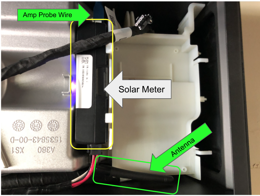
CT-1 Amp Probe Wire
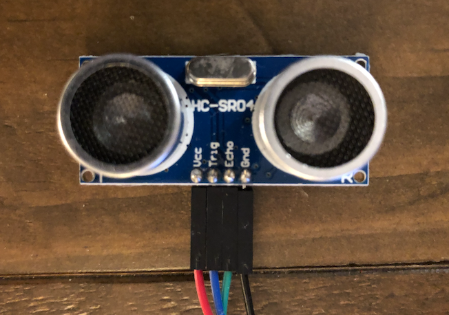
The Neurio has a wire plugged in to the top in the CT-1 (current transformer) port. I traced it over to the solar inverter where a clamp is wrapped around the solar inverter output AC line to measure the amperage. I re-seated that connector.
Antenna
I then noticed that there was an antenna jammed below it that was tucked to the left, under the massive metal inverter shield. I turned the antenna to the right, in the open unshield space.
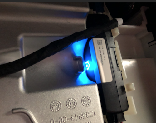
As soon as I did these two things, the LED “n” on the box began to change and a tune started coming out of the box. It sounded like “I am connected now”. The flashing “n” became a solid blue light.
Eureka!
I went back to the System screen and re-activated the Solar Assembly by clicking “Enabled”. This takes several minutes and you will see the system go through and activate the solar arrays, test relays and impedance before the assembly comes online.
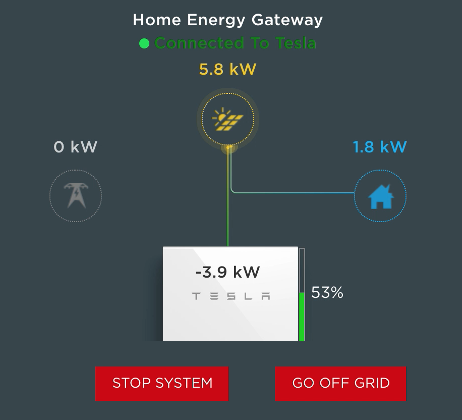
As soon as the Solar Assembly came online, I started seeing kW of power show up on the Systems screen. 5800W of power was coming in, fully powering the house and charging the Powerwalls!
Not so fast…
Sadly, just two hours later my elation was destroyed. The solar energy dropped back to zero.
I checked the inverter. Sure enough, the Neurio was flashing again. I attempt the above process again, several times, but no joy this time. It would chime and go green, but then started flashing again. Based on my research, the Neurio connects to the Tesla Gateway WiFi only. The beeps and flashes indicate that it is unable to connect to the Gateway WiFi.
One thought I had was to reach out to Neurio (which is now owned by Generac) to see if they could provide the API, pinout or schematics for the W2 device so I could troubleshoot at the firmware and component level. When I contacted them, Generac replied that the serial number for my device contains proprietary firmware by Tesla that they cannot support. They recommend that I contact Tesla at: 888-518-3752. Oh well, it was worth a shot.
The Workaround
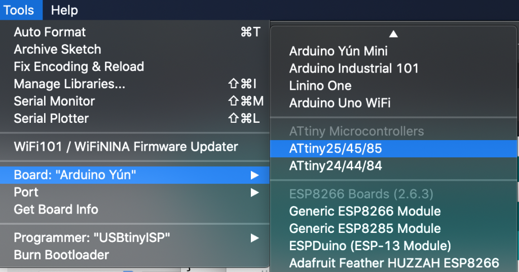
I love a challenge. In fact, when something isn’t working, it is almost an addiction to me. I have to figure it out and fix it! So, I had two thoughts at this point. First, I wanted to see what the Neurio was actually doing. I thought about setting up an ESP8266 to be an WiFi access point to intercept the Neurio’s communication attempts with the Gateway. But before I do that, it occured to me, I wonder what would happen if the system didn’t have a solar meter at all. In my investigation, I discovered that the solar power meter feature is often an add-on or post-install enhancement. Maybe this was more of an add-on feature than a requirement?
At the minimum, I wanted to see if there are alternatives to the Neurio in the Tesla configuration. Unfortunately, there isn’t an easy way to edit this data. I discovered that settings could only be set during the initial setup time. That would require running the setup wizard again. I decided to be bold and fire up the installation Wizard. At the bottom of the system portal is the “Run Wizard” link. Of course, I clicked it.

WARNING: I’m fairly confident that you can completely break your Tesla Solar setup using the Wizard, maybe even disable power to your house permanently. It is intended for installers. I’m taking the risk, but you should consider this first and be cautious about proceeding. I’m also fairly confident I’m going to void something in the process, but if you put something in my house, fair game, I must hack.
The wizard is straightforward. It requires you to Stop the system, but the settings are mostly intuitive. When I arrived at the Meter screen, it had 3 different meters displayed. I apologize, I did not take screenshots but will update this blog if I capture them in the future but the screens are very basic.
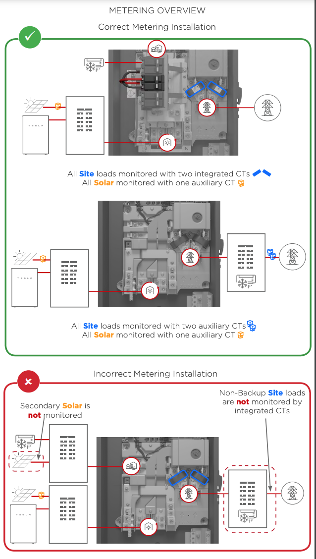
Two of the sensors were for the built-in CT’s used to measure the power in the Tesla Backup Gateway (you can see them on the main bus if you open the Gateway panel – which I did).
DANGER: High voltage – Seriously!
These tested extremely fast (subsecond) were working correctly and tested “good”. The third meter, a WiFi meter, was the Solar Meter (Neurio) and it’s status was Error, unable to connect. I clicked the connect button which reported it would take 3 minutes to configure the WiFi sensor. No shock, it didn’t work. I tried it 3 more times. The “Advanced” drop down allows you to add MAC address and IP, but this didn’t help. There was a “Delete” button. I thought it might be worth a try to delete and re-add. At the bottom were options to add “WiFi” or “Wired” CTs. I tried to add the Neurio (WiFi) again, multiple times, rebooting the Neurio occasionally to see if that would help. Nothing.
Here is where something interesting happened. The Wizard would NOT let me advance because the WiFi sensor was not healthy (connected). Hum… Well, I figured I would just have to delete it to see what other screens I could find in the Wizard. I deleted the Neurio. I advanced to the next screen and was presented with a “Warning – you do not have a solar sensor selected.” Naturally, I ignored that and continued.
Commissioned! I completed the Wizard setup and the system came back online. Surprisingly, the system screen looked basically the same but the dynamic flow diagram was actually working. There were no sensor errors or warnings. Power was flowing from the Grid to the House. It was the middle of the night so I signed off and went to bed.
I know what you are thinking. This is dangerous, right? I mean, we seemed to have removed solar power observability from the platform. Will the Gateway and Inverter sill know what to do? Well, it turns out… it does!
The Power of the Sun
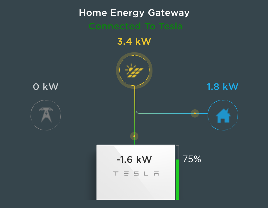
Next morning, I woke to discover solar generation was charging the powerwalls and our house was completely powered by the sun! I still want Telsa to fix the Neurio or, better yet, provide some hardwire CT to monitor Solar power generation. I’m assuming that the display below means that the Gateway is computing the the solar generation based on other CTs. In any case, my workaround is in place and we now have a working system again.
As I’m looking at my phone, I realize… I’m holding the power of the sun in the palm of my hand. Yes, that is a geeky Doc Ock reference. We are now powering our home with an ancient but reliable and self-regulating, thermonuclear fusion reactor… our sun.
The Return of Tesla
1 November 2021
I gave up on waiting on Tesla to respond to me about the Neurio. I figured it didn’t matter since I had a working system. A month after the install and I still didn’t have an inspection date. Then it happened. I received a text message and email from Tesla that my inspection was scheduled. There was NO DATE or TIME given. Instead of asking, I figured it didn’t matter. We would see what would happen.
The day of inspection had arrived. A surprise knock on the door and there was Ishmael from Tesla. He explained he was there to meet with the City inspector for the final inspection. I showed him the gear, the Powerwalls, the gateway and the breaker panels. He looked at me and asked, “Did the install crew not put on the warning labels?” Nope.
This was something I had noticed after the installers left. In the Tesla plans are specific instructions on where to place the red warning labels on all of the gear. It includes a helpful diagram for anyone wanting to know how to kill all power in case of emergency. I had raised this issue with my project advisor a few times, but as usual, told me he would look into it and of course, nothing happened. I explained this to Ishmael who rolled his eyes and expressed apologies and said he would need to call to get the labels or it would not pass inspection. He would wait for the delivery and get them installed and ready for the City.
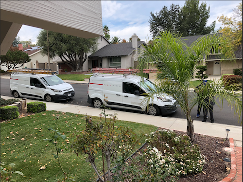
Shortly after meeting Ishmael, another Tesla vehicle pulled up. I figured it was the inspection stickers, but instead, it was Rocío, a Quality Assurance technician. She told me that her job was to make sure everything was installed correctly and running. I almost hugged her! I expressed my delight and appreciation that she would check on us. I explained everything that happened including how the installers said it must have been a Tesla software bug and gave up after trying for hours to get it work. I also told her about the Neurio hack I had done to get it working. She was shocked, sympathetic and determined to fix the issue.
Naturally, Rocío attempted to reset the Neurio and discovered the same thing that I did, with the exception that she was able to get the Neurio to work if she held the connector, pressing on it in a certain way. “There is clearly something wrong with the hardware and it needs to be replaced,” she concluded. I hate to be cynical, but I was definitely thinking this new chapter in my Tesla adventure would turn into an multi-week RMA, repair order and a return visit that may get scheduled sometime next year, if I’m lucky.
To my delight, Rocío looked straight at me and said, “And we’re going to get this fixed today!” She was right! She made a phone call and 30 minutes later another Tesla van showed up with the replacement Neurio!
Rocío got it working. Less than 30 minutes later she had the entire system back online and working correctly. “That’s amazing!” I told her. She clearly saw my astonishment and said, “I used to be an installer, I know what’s needed.” Well, that was completely accurate. She didn’t stop there. She examined all the gear and climbed up on the roof to ensure all the panels were in good order.
Shortly after the good news, the warning labels arrived and were attached to the new gear, ready for the official inspection. I started passing out my sincere appreciation, candy bars, water and Gatorade to these brilliant Tesla soldiers that had come to save the day. After bidding farewell to our new friends, Rocío drove off on her shiney white stallion… uh, I mean Tesla van.
About 30 minutes later, the City Inspector arrived and after a quick survey of the installed gear with Ishmael, signed his approval. Now we are on to the Permission to Operate (PTO) by Southern California Edison.
Power Gremlins
3 November 2021
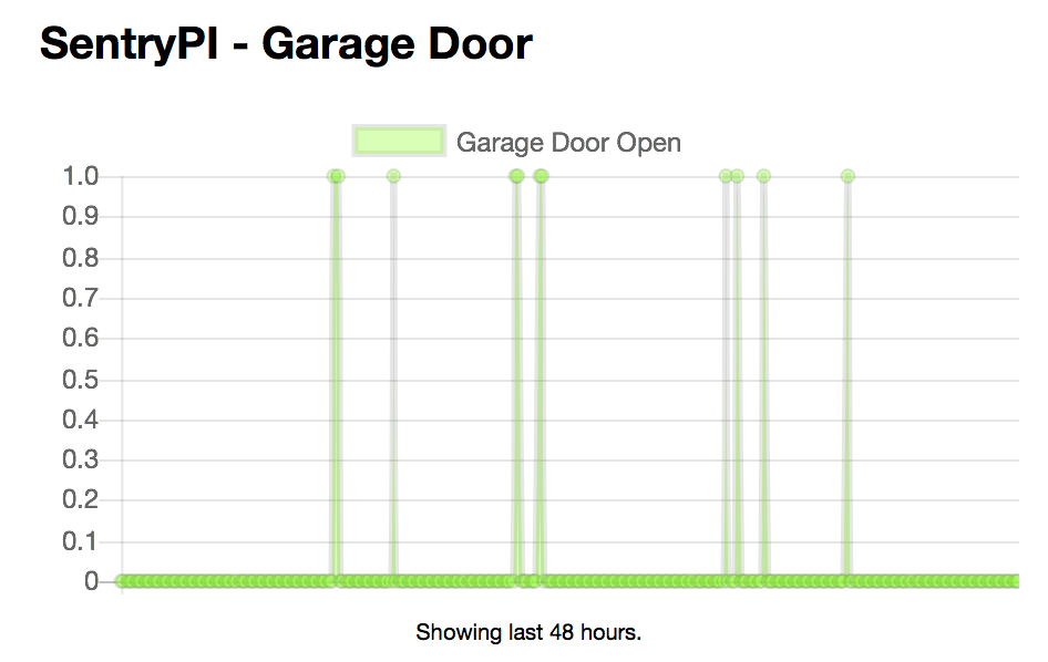
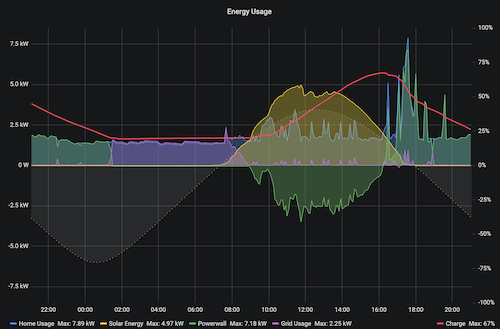
I should definitely learn to be more guarded in my optimism about this Tesla adventure. After two days of having the new Neurio re-installed, I started noticing something odd. After solar production when I would expect the Powerwalls to kick in and power the house, I would see grid power start to show up and the Powerwalls drop to zero. It would only last for a few minutes then return to normal operations. Looked at the Powerwall Dashboard I set up and can even see the grid power spiking during the day when solar production was more than enough to power the house.
These just started showing up after the new Neurio was installed.
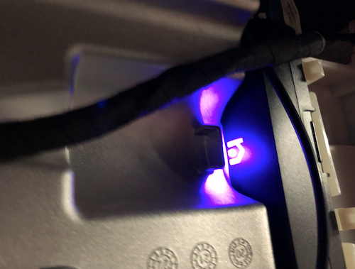
The grid power spikes did not exist before the new Neurio. I went out to look at the inverter. The Neurio’s purple light was mostly solid but would “flicker” blue. It was random, like a candle flame not like the error condition of the previous Neurio. It was happening constantly as I watched. When the flickering would get bad, I would see the powerwall drop to zero and grid power surge. There seemed to be a correlation. At any rate, I wasn’t going to let the flickering continue.
HIGH VOLTAGE WARNING: I need to stop here again and remind everyone that these systems contain extremely high voltages and are dangerous. Hopefully it goes without saying, but please be careful if you poke around inside these electrical boxes. High voltage can be fatal.
I powered off the Neurio by unplugging the power next to the antenna at the bottom. I noticed the antenna was once again tucked under the massive shield. I guess that was the typical install. I changed it so it was pointing away from the inverter shield and reworked the cables to plug it back in. The Neurio went through the startup (flashing, then solid green, then blue and then purple). I watched it for a while and noticed it stayed solid purple, no flickering.
I don’t know if this was a fix or a sign of things to come. Other people have reported similar problems with the Neurio, including a YouTube video on how to reset it the way I did. It is rather shocking how unreliable this little box is. I understand it is a “revenue grade” meter which is likely why Tesla is using it, allowing them to report “Solar Renewable Energy Credits” (SRECs). The Inverter itself seems to have a decent meter without the Neurio which is why my workaround hack worked while waiting for the Neurio replacement. If the reset doesn’t work, I will likely revisit my “fix.”
5 January 2022
The “fix” was temporary. It appears to be a resource leak that requires the Neurio to be restarted. The good news is that Tesla finally recognized the instability and sent out a 21.44 firmware update that fixed the Powerwall from disabling solar when the Neurio goes into a bad state. Finally! I was planning on ripping the Neurio out after PTO, but now I don’t have to do that. I’m currently on firmware 21.44.1 and just heard from the community that others are seeing an upgrade to 22.1 that also upgrades the Neurio from firmware “1.6.1-Tesla” to “1.7.1-Tesla” (you have to access the vitals API and decode the protobuf binary payload to see this – see here). Hopefully that helps with stability.
Permission to Operate
2 February 2022
PTO, finally! Our utility company, Southern California Edison (SCE) granted permission to operate. It took Tesla several tries to get the PTO request submitted correctly. SCE was notifying us of all the transactions but we were not able to see the full application or help. Believe me, I tried! In any case, our installation adventure has finally come to an end. It has been seven months since we started this epic journey. It is good to finally have a fully operational system.
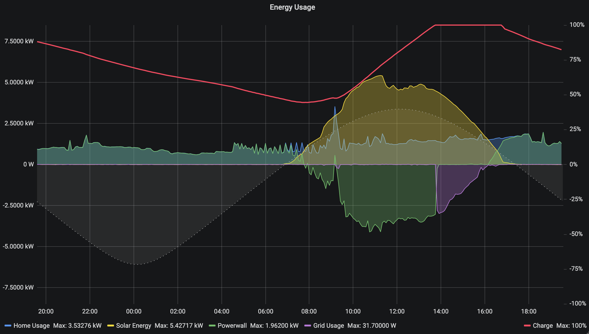
To be fair, we have had a working solar system with Powerwall backup since October, but without PTO. PTO means that our system is no longer in self-consumption test mode. We can now push excess solar production to the grid for a credit. For the first time ever, we see grid graph going negative!
Conclusion
The Tesla Solar system has been an adventure for us. I don’t regret going with Tesla even though they have improvement areas, especially related to consumer experience. We love the look of the panels and the equipment. In typical Tesla fashion, the design is stunning and feels like quality. If you do select Tesla Solar, my advice is to plan on being the project manager. Stay on top of the details to keep things moving and make sure items are not dropped.
Regardless of who you go with, I recommend you set some non-negotiables to help you filter. Here were my non-negotiables:
- Aesthetics – We wanted something that looked high-tech, neat, clean and symmetrical on our roof. I wanted the dark panels (no white lines) with a clean looking frame.
- Whole House Backup – We wanted batteries capable of running our house over 24 hours in the event of a power outage and a system that would charge the batteries during the day even if power was out for extended days.
- Home Automation and Monitoring APIs – I wanted a system I could hack, use tools to monitor, dashboard, trend and even make decision on home automation components to optimize our energy usage.
- Off the Grid – We wanted the system sized to allow us to be self sustaining with no need to use the grid even at night, fully expecting that at some point Net Energy Metering disappears or becomes less attractive, the system will still provide us with a zero grid usage option.
This helped considerably. It eliminated the list down to a handful and the lowest cost on our list was Tesla, who also had the best aesthetics IMHO. Now to be clear, as I mentioned above, Tesla is seeing explosive demand for their option and their customer service struggles a lot. I also had the opportunity to work with several incredible Tesla technicians who helped us.
I am extremely happy with our Tesla system and would recommend it to anyone, despite the bumps along the way. Tesla hit on all my non-negotiables and is elegant, fun and powerful. It has become a delightful hobby as well as a powerful utility for our green energy mission.
While a similar adventure may not be for everyone, if you are in the market for a Solar system, I still highly recommend checking out Tesla’s options. Use this link and you can save $300 if you do order and I get a reward too: http://ts.la/jason50054
I have to confess. I love toys. To me, this new Tesla Powerwall+ Energy systems is a gigantic (and expensive) toy. I have thoroughly enjoyed tinkering with the system and building electronic accessories and software to manage it. As you have seen in this post, I wrote my own python API library (pyPowerwall) and created a Powerwall Dashboard to better see what the system is doing over time (credit to other open source projects I mention below).
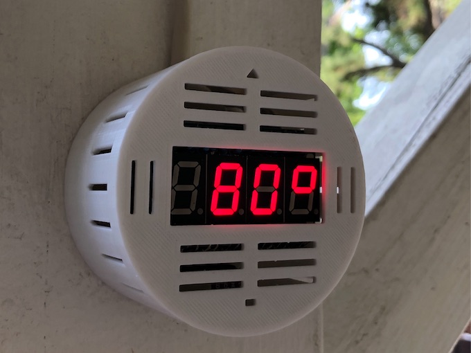
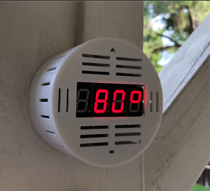
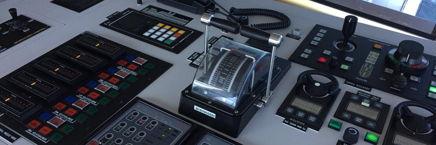
One thing that the Tesla is missing is a good instrument panel display. Sure, you can run the app all the time, but I wanted something that would show the solar production and other details like a physical dashboard but without opening an app. I built one. It is hanging next to the Powerwalls in our garage. Much to my wife’s initial trepidation, I also built one and hung it in our kitchen. It turns out that I’m not the only one to appreciate it… well, after a while anyway. 🙂
Here are some of my toys that I gladly share with you. Please reach out and let me know if you find these useful:
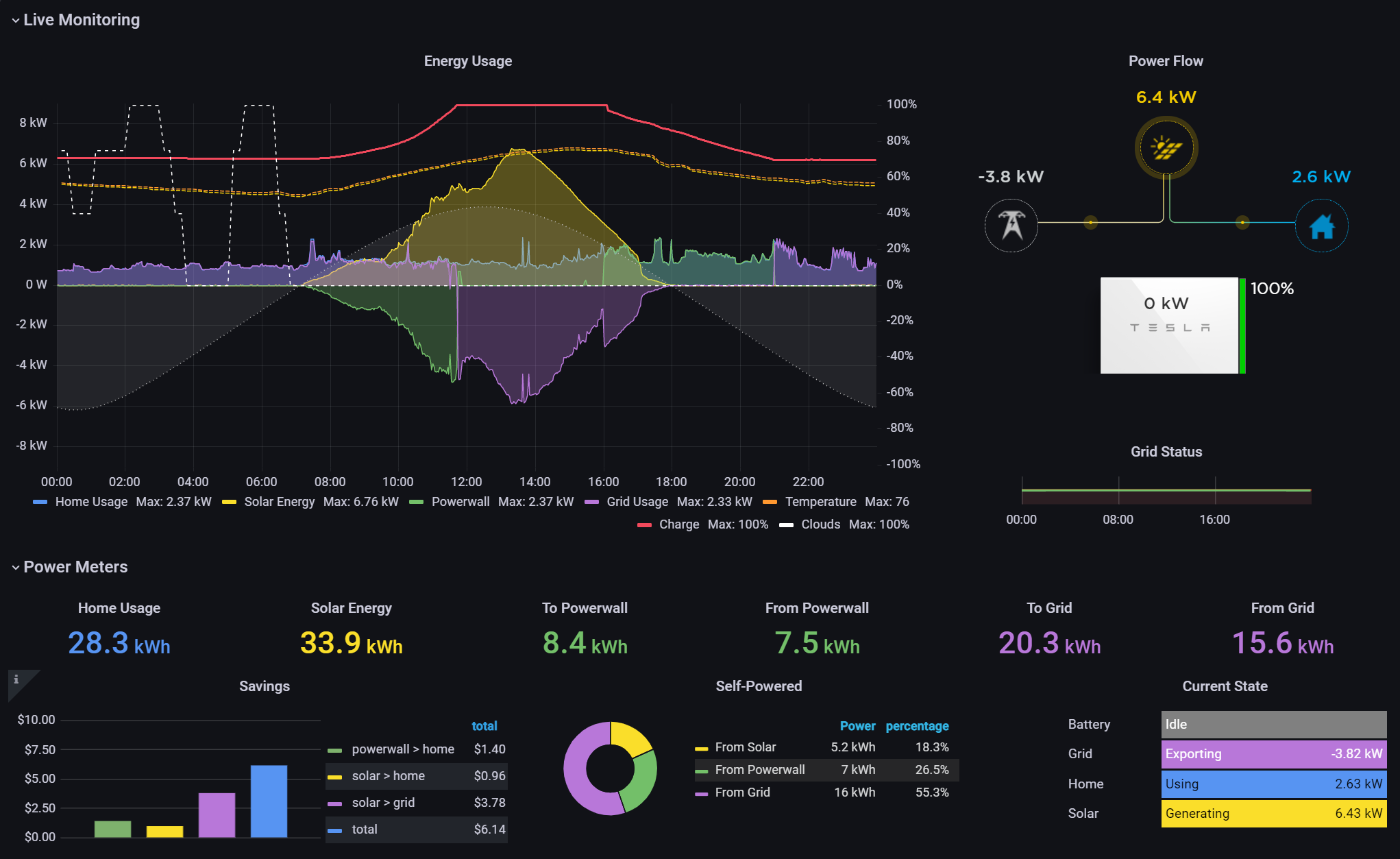
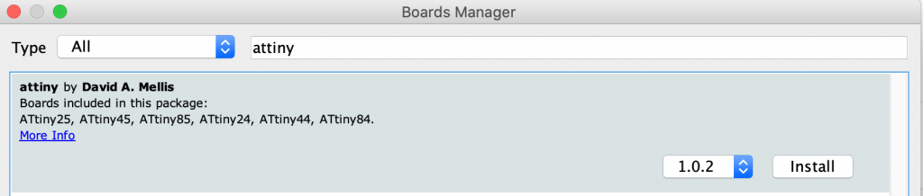
Powerwall Web Dashboard – The Tesla App and web based portal present great animations showing the solar generation and usage. However, the information is very limited and not design for visualizing the energy data in multiple ways. I wanted to see a year at a glance as well as the string data (how much power each group of solar panels on the roof are producing). I found this Grafana based dashboard and made some minor changes including the addition of my own python based Powerwall API Proxy. Here is a simple python API module pyPowerwall to pull data from the Powerwall Gateway using your “customer” credentials: https://github.com/jasonacox/pypowerwall. If you are wanting your own Powerwall Dashboard, it is fairly easy to set up with the instructions here using Docker Compose: https://github.com/jasonacox/Powerwall-Dashboard#powerwall-dashboard
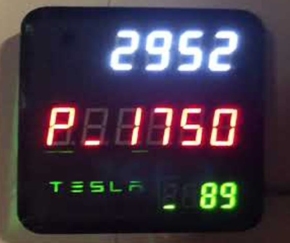
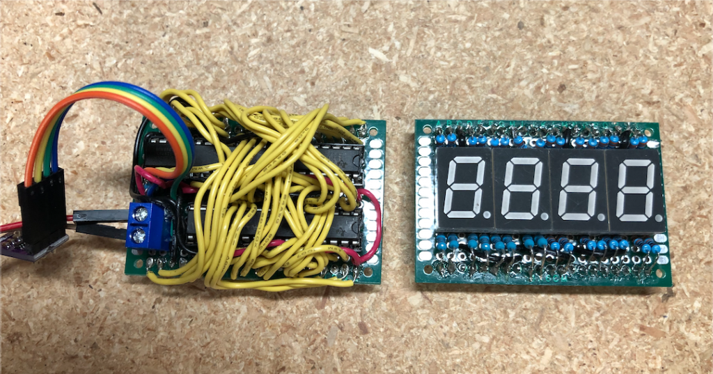
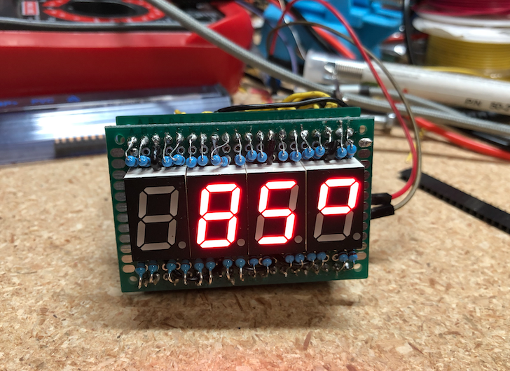
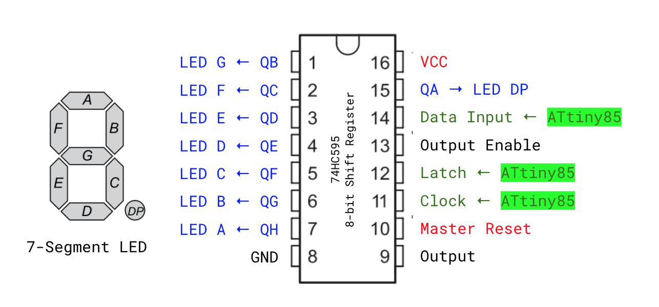
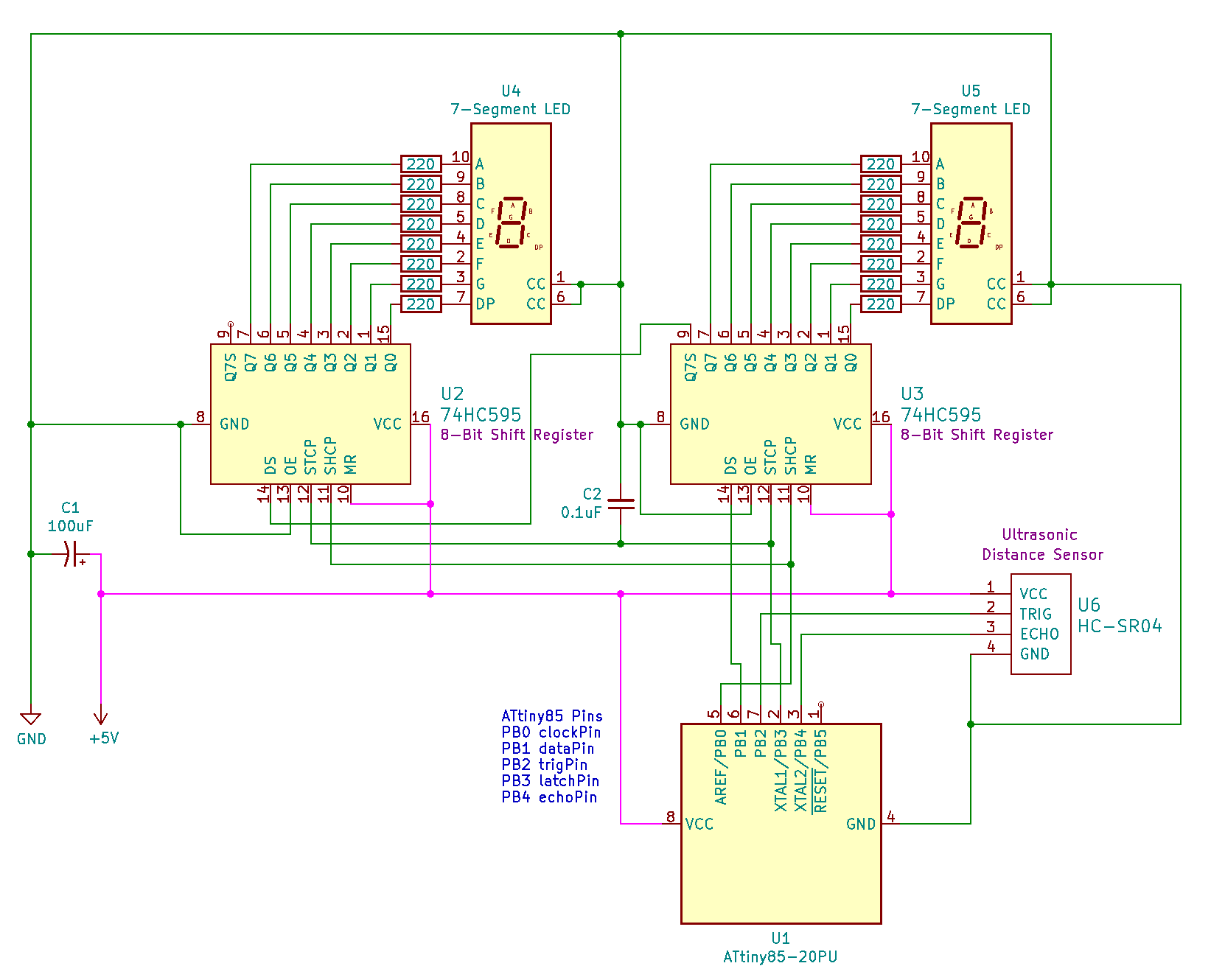
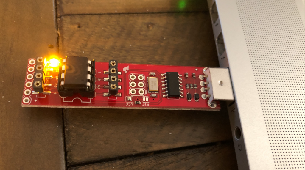
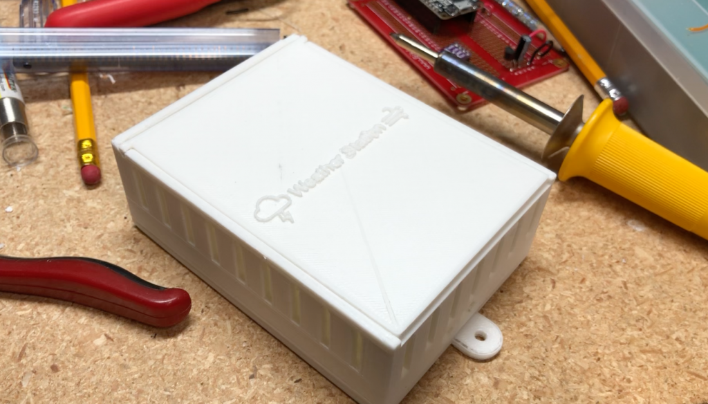
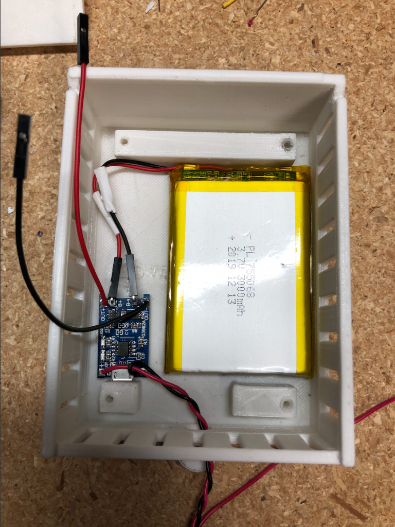
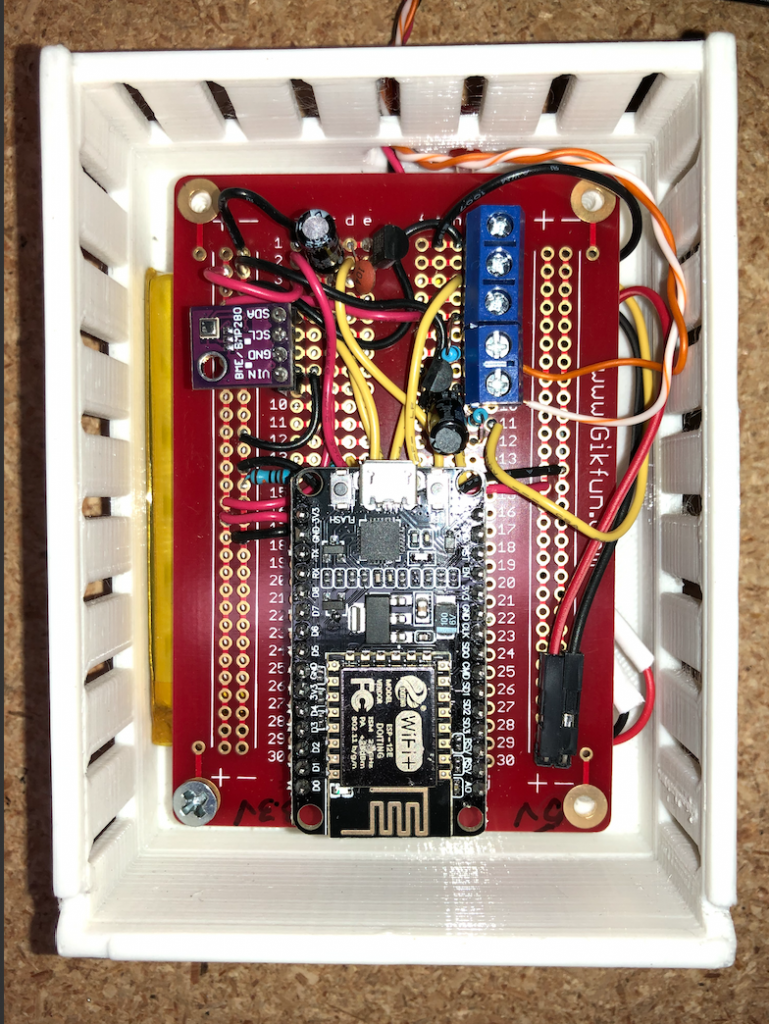
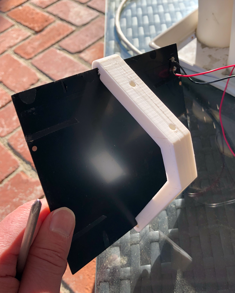
Powerwall Wall Mounted Display – I really wanted to see the current solar generation and state of the Powerwall on a simple LED digital display. I 3D printed a Tesla themed case and installed the displays to show solar, house, battery, and grid power data. The display show the solar production power at the top. House, Powerwall and Grid power data rotate through the middle display and the battery level of the Powerwalls is at the bottom (89% in this picture). You can see a video of the display running below.
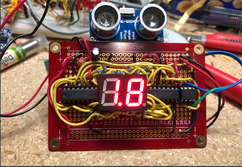
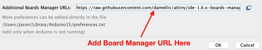
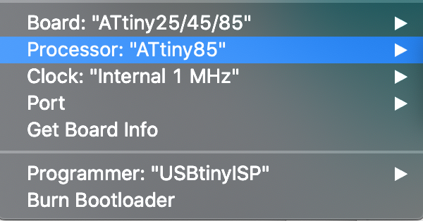
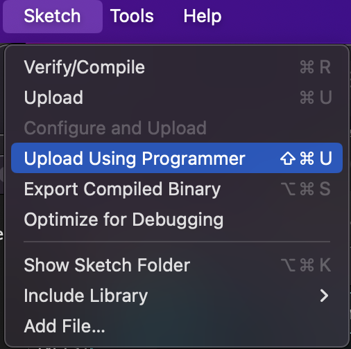
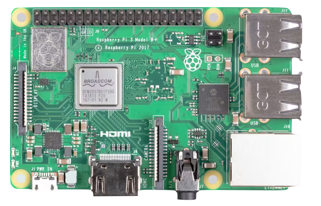
The display uses a WiFi enabled systems-on-chip (SoC) ESP8266 WeMos controller and three simple TM1637 7-segment LED display modules. Naturally I used my own Arduino API library (TM1637TinyDisplay) for those and the pyPowerwall proxy to display the results. It would have been nice if Tesla had built a wall monitor to show vitals like this. I’m sure it would have been a nice animated OLED display of some sorts. But this was fun. I needed to build another toy and I love my retro-LED display. If you want to build your own, I have open sourced the design and code and uploaded here for you to use: https://github.com/jasonacox/Powerwall-Display
I took note of several areas of concern and improvement during my investigation and problem solving. I have recorded them here.
- WPA TKIP Command Access Point – The Tesla Gateway uses this weaker method to host its WiFi access point. As I discovered the Neurio uses this same access point to send Solar Power data (if it works). WPA TKIP has been dropped due for security reasons and more modern access points use WPA2 and AES encryption (WPA2-AES).
- HTTPS Security Certificate – The HTTPS certificate the Gateway uses will create a browser warning (or error) when you go to the system control portal, either via your home network or via the access point at https://192.168.91.1.
- Second Factor – For setup, the user is required to toggle the switch on a Powerwall as a 2nd factor to prove authorization, which is a good thing. That works well for me since my Powerwalls are locked in my garage, but if your Powerwalls are outside next to the Gateway, an attacker on-location could easily join and toggle without you even knowing.
- IoT Sensors – The main problem on my system was the Neurio W2 WiFi based sensor. This IoT device sends back power data it measure to the Gateway controller. Generally, this is an elegant way to handle transmitting sensor data between systems without having to wire things. The irony is that the Gateway and Inverter already have several wires and control signal between them. Why not add another wire and avoid any WiFi communication outages? Hopefully I will be able to replace my Neurio with a wired solution.
- Solar System Plan – I asked the Tesla Advisor to provide me with the design plans developed for the City Permit. They do not provide this without asking. I am glad I asked. The plans have all the schematics for the wiring as well as the layout. I discovered several things that I wanted changed and was able to get them to update before they came onsite. If you wait until they come onsite, they may not have the materials to make the adjustment and, worse, could charge you for any changes.
I found the following github projects, references and diagrams during my investigation into my Tesla Solar Adventure. I’m pasting them all here to be helpful for anyone else experiencing the same problems. The information may not be directly related but could provide a clue.
Github Projects
- pyPowerwall (shameless plug) – Python Module to pull data from the Powerwall Gateway using your customer credentials: https://github.com/jasonacox/pypowerwall
- Powerwall Dashboard (2nd shameless plug) – Grafana based dashboard project that let’s you visualize and drill into the Powerwall+ data – https://github.com/jasonacox/Powerwall-Dashboard#powerwall-dashboard
- TESLA PowerWall 2 Security Shenanigans – https://github.com/hackerschoice/thc-tesla-powerwall2-hack
- Tesla Powerwall 2 – Local Gateway API documentation – https://github.com/vloschiavo/powerwall2
- Powerwall Monitoring – https://github.com/mihailescu2m/powerwall_monitor
- Python Tesla Powerwall API – https://github.com/jrester/tesla_powerwall
Neurio W2 LED Indicator
Tesla Powerwall Installation – Metering Installation (link)