After discovering the tiny but mighty ATtiny85 microcontroller, I decided to put it to use to help me park my car in the garage. Sure, I could continue to use the softball hung from the ceiling to let me know when I have the car pulled in far enough, but why not take advantage of some tech and have it show me instead? Alternatively, for these times, it is also a fun way to clearly demonstrate 6ft social distancing. 😉
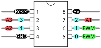
ATiny85 Microcontroller
The ATtiny85 has 5 GPIO easily usable pins (technically you can even use Reset pin as a 6th GPIO but that makes it much more difficulty to reprogram). For information about how to program the ATtiny85, see my previous blog post here.
For my “Parking Helper” project I decided to use the low cost entry level ultrasonic distance sensor, the HC-SR04 and two 7-Segment LEDs to show the distance between the device and the front of the car.
HC-SR04 Ultrasonic Sensor
The HC-SR04 has 4 pins: VCC, Trig, Echo and Gnd. The Trig and Echo lines will be driven by the Attiny85.
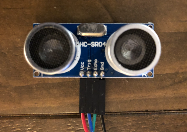
The HC-SR04 measures distances by sending (TRIG) an sound pulse and measuring the time it takes for the ECHO. Sound travels through air at 332 meters per second at 20 °C (68 °F). Using this the unit provides a duration pulse back to the controller that can be used to determine the distance.
The speed of sound is: 343m/s = 0.0343 cm/uS = 1/29.1 cm/uS
I found a great project here where the author uses the HC-SR04 as an ultrasonic rule. Using the ATtiny85 to trigger and receive the duration pulse we can determine the distance to the parked car.
// Send TRIG HIGH for 10 microseconds
// to trigger the HC-SR04 to send a sound pulse
  digitalWrite(trigPin, LOW);
  delayMicroseconds(2);
  digitalWrite(trigPin, HIGH);
  delayMicroseconds(10);
  digitalWrite(trigPin, LOW);

// Read the ECHO duration
  duration = pulseIn(echoPin, HIGH);

// convert the duration to cm
  distance = (duration / 2) / 29.1;
LED Display (2 Segment)
Driving the display with two 7-segment LEDs is a bit more complicated. Each segment has 7 LEDs to form the numbers plus one LED for the decimal point. That would require 8 GPIO ports for each LED Display or a total of 16 GPIOs! The ATtiny85 has only 5 available for use so we need another way. Thankfully, we can use two low cost 8-bit shift registers (74HC585) and get by with using only 3 GPIO and still drive the 16 LEDs on the two displays.
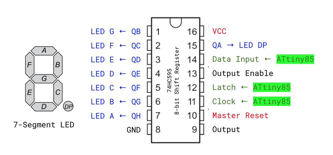
Here is how it works… The ATtiny85 sends the binary data for the the numbers to a first 74HC595 8-bit register using its “Data Input,” “Clock” and “Latch” lines. Once the register receives a total of 8 bits (1 byte), it will overflow the data out through its “Output” line which can be connected to the “Data Input” of another register.
We toggle the “Clock” to signal to the registers to record the value of the data line (1 or 0). We do that for each of the bits of the two bytes we need sent for each display. Finally, we have the ATtiny85 toggle the “Latch” to let the registers know when the transmission is complete. They then lock the 8 output lines (QA to QH) to high or low depending on what they recorded. These lines are connected to the individual LEDs on the 7-segment LED displays.
I found a great example of using the 74HC595 to drive multiple LED Displays here. I used that code to send the data as well as the byte arrays used to form the numbers on the LEDs. Since that project was using a common anode LED and my project uses a common cathode LED I had to flip the bits. In the code below, a one (1) value would drive the LED high (on) and a zero (0) would drive it low (off).
/* Set up 7-segment LED Binary Data

     |--A--|
     F     B
     |--G--|
     E     C
     |--D--|   H - Decimal

     0b00000000
       ABCDEFGH
  */
  numArray[0] = 0b11111100; // 0 - Zero
  numArray[1] = 0b01100000; // 1 - One
  numArray[2] = 0b11011010; // 2 - Two
  numArray[3] = 0b11110010; // 3 - Three
  numArray[4] = 0b01100110; // 4 - Four
  numArray[5] = 0b10110110; // 5 - Five
  numArray[6] = 0b10111110; // 6 - Six
  numArray[7] = 0b11100000; // 7 - Seven
  numArray[8] = 0b11111110; // 8 - Eight
  numArray[9] = 0b11110110; // 9 - Nine
  numArray[10]= 0b00000000; // All Off
Circuit Schematic
Pulling it all together, here is a schematic I put together that combines the ATtiny85 with the two 74HC595 registers, two LED displays and the HC-SR04 ultrasonic sensor.
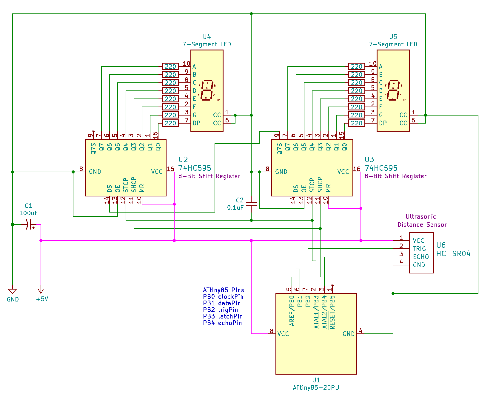
A Kicad schematic is included in this project and the schematic export is sown above. The circuit is powered with a steady 5V DC supply (e.g. USB adapter). The HC-SR04 is an entry level sensor and does suffer from some fluctuation. Logic in the code attempts to stabilize the measurement by making multiple readings.
List of Materials
- 1 x ATiny85 Microcontroller (DigiKey)
- 2 x 74HC595 8-bit Shift Register (DigiKey)
- 1 x HC-SR04 Ultrasonic Distance Sensor (DigiKey)
- 2 x 7-Segement LED Display CC (DigiKey)
- 16 x 220 Ohm Resistor
- 1 x 100uF Electrolytic Capacitor (DigiKey)
- 1 x 0.1uF Ceramic Capactior – (Amazon)
Code
The code for the project can be found on GitHub: https://github.com/jasonacox/UltrasonicDistanceDisplay
Imperial and SI Units
In Imperial unit mode, the code is written to display distances in inches (1 to 11) for distances less than 1 foot. Once the distance reaches 1 foot, it will show feet in decimal (1.0 to 9.9) until the distance reaches 10 feet when it will display in feet only (e.g. 10).
In SI unit mode, it will show centimeters for distances less than 1 meter (1 to 99, then it will show meters with decimal (1.0 to 9.9) until the distance reaches 10 meters and will continue to show meters only.
To toggle Units: Hold the distance to 4 (either unit) for ~4 seconds and it will toggle between units. Imperial mode will flash “in” and SI mode will flash “c”.
Sleep Feature
Sleep Mode: The code includes logic to turn off the display when there is no movement and power back on when movement is detected.
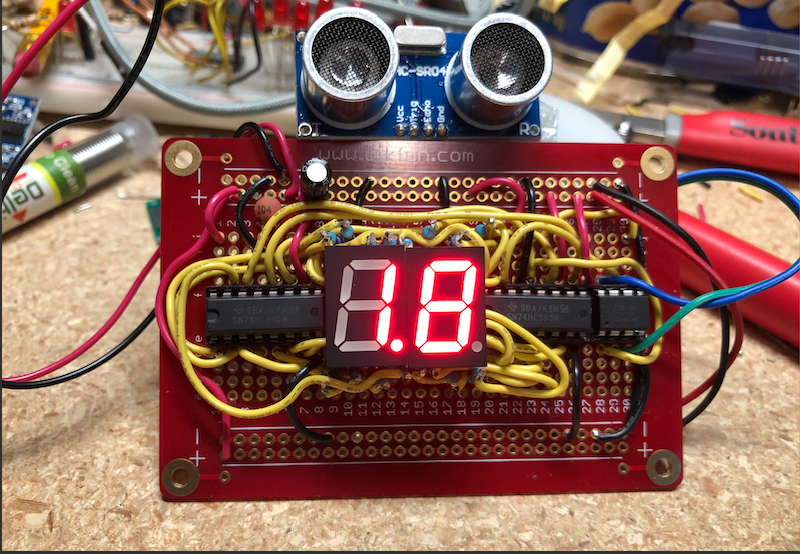
Prototype