“One step to the edge of impossible. And then, further.” – National Geographic
There has been a lot of excitement in the scientific community these last several weeks. First, there is the constant buzz about AI and the pending birth of a real-life artificial general intelligence like Marvel’s fictional J.A.R.V.I.S. (which is just a rather very intelligent system by the way). Then there is this incredible medical news about the experimental anti-cancer drug, Dostarlimab, which had an unprecedented 100% success rate in eliminating tumors. Imagine what that could do for our human family! And now, just this past week, we saw the excitement building over LK-99, a polycrystalline compound that was reported by a team from Korea University to be a room-temperature and ambient pressure superconductor.
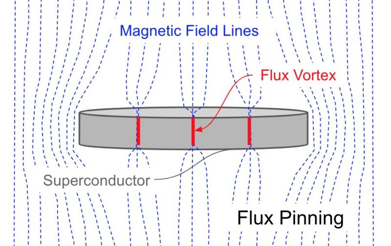
The LK-99 news was particularly fascinating to me. And I’m not alone. The scientific community is buzzing about it and excitedly conducting experiments to replicate to confirm or disprove the discovery. One of the things they hope to observe is “flux pinning”. Have you ever heard of flux pinning? Well, I hadn’t, so I decided to check it out. It turns out that flux pinning is a characteristic of superconductors where magnetic flux lines are trapped in place within a material’s lattice structure (quantum vortices). This flux pinning locks the superconductive material within a magnetic field, causing it to levitate. Can you imagine whole worlds built of this material? It may look a lot like Pandora from Avatar! More importantly this leads to benefits like enhanced current-carrying capabilities, higher magnetic field tolerances, and reduced energy losses.
Implications are mind blowing! If a room temperature and ambient pressure superconductor can be fabricated, we could see things like massively reduced losses in power transmission, higher performing electromagnetic devices (e.g. MRIs, motors, generators), revolutionized transportation systems (e.g. maglev trains, lightweight and energy-efficient propulsion systems), faster low-power computing devices and of course, new insights into the fundamental nature of matter and the universe. Of course, LK-99 may not be the superconductor we are looking for, but the quest continues… and we are learning!
I love science! The systematic rigor, the tenacious pursuit of discovery, and the passionate pursuit of understanding our universe is who we are. We thirst for knowledge and hunger for new abilities. It motivates us. It propels us to adapt. It allows us to survive and thrive when conditions are threatening. It is our genius, and perhaps at times, our curse. We are restless and unsatisfied. But that insatiable curiosity compels us to discover, to explore, to test, to add to our knowledge, to create and become more than we were.
Look, I know I’m incurably optimistic to a fault. I know that there are disappointments and failures ahead of us as well. And to be fair, the path to the future can sometimes seem impossible. But oddly enough, it is at those moments that we discover something different and something new. We see, we learn, we step to the edge and we go further! The unlimited future awaits. Let’s go!
Every week, we hear announcements of new AI powered tools or advancements. Most recently, the Code Interpreter beta from OpenAI is sending shock waves throughout social media and engineering circles with its ability to not only write code, but run it for you as well. Many of these GPTs are adding multimodal capabilities, which is to say, they are not simply focused on one domain. Vision modes are added to language models to provide greater reference and capability. It’s getting hard to keep up!
With all this progress, it makes you wonder, how close are we to Artificial General Intelligence (AGI)? When will we see systems capable of understanding, learning, and applying knowledge across multiple domains at the same level as humans? It seems like we are already seeing systems that exhibit what appears to be cognitive abilities similar to ours, including reasoning, problem-solving, learning, generalizing, and adapting to new domains. They are not perfect and there are holes in their abilities, but we do see enough spark there to tell us that the journey to AGI is well underway.
When I think of AGI, I can’t help but compare that journey to our own human journey. How did each of us become so intelligent? Ok, that may sound presumptuous if not a bit arrogant. I mean to say, not in a brag, that all of us humans are intelligent beings. We process an enormous amount of sensory data, learn by interacting with our environment through experiments, reason through logic and deduction, adapt quickly to changes, and express our volition through communication, art and motion. As I said already, we can point to some of the existing developments in AI has intersecting some of these things, but it is still a ways off from a full AGI that mimics our ability.
Instincts
We come into this world with a sort of firmware (or wetware?) of capabilities that are essential for our survival. We call these instincts. They form the initial parameters that help us function and carry us through life. How did the DNA embed that training into our model? Perhaps the structure of neurons, layered together, formed synaptic values that gifted us these capabilities. Babies naturally know how to latch on to their mothers to feed. Instincts like our innate fear of snakes helped us safely navigate our deadly environment. Self preservation, revenge, tribal loyalty, greed and our urge to procreate are all defaults that are genetically hardwired into our code. They helped us survive, even if they are a challenge to us in other ways. This firmware isn’t just a human trait, we see DNA embedded behaviors expressed across the animal kingdom. Dogs, cats, squirrels, lizards and even worms have similar code built in to them that helps them survive as well.
Our instincts are not our intelligence. But our intelligence exists in concert with our instincts. Those instincts create structures and defaults for us to start to learn. We can push against our instincts and even override them. But they are there, nonetheless. Physical needs, like nutrition or self preservation can activate our instincts. Higher level brain functions allow us to make sense of these things, and even optimize our circumstances to fulfil them.
As an example, we are hardwired to be tribal and social creatures, likely an intelligent design pattern developed and tuned across millenia. We reason, plan, shape and experiment with social constructs to help fulfil that instinctual need for belonging. Over the generations, you can see how it would help us thrive in difficult conditions. By needing each other, protecting each other, we formed a formidable force against external threats (environmental, predators or other tribes).
What instincts would we impart to AGI? What firmware would we load to give it a base, a default structure to inform its behavior and survival?
Pain
Pain is a gift. It’s hard to imagine that, but it is. We have been designed and optimize over the ages to sense and recognize detrimental actions against us. Things that would cut, tear, burn, freeze and crush us send signals of “pain.” Our instinctual firmware tells us to avoid these things. It reminds us to take action against the cause and to treat the area of pain when it occurs.
Without pain, we wouldn’t survive. We would push ourselves beyond breaking. Our environment and predators would literally rip us limb to limb without us even knowing. Pain protects and provides boundaries. It signals and activates not only our firmware, but our higher cognitive functions. We reason, plan, create and operate to avoid and treat pain. It helps us navigate the world, survive and even thrive.
How do we impart pain to AGI? How can it know its boundaries? What consequences should it experience when it breaches boundaries it should not. To protect itself and others, it seems that it should know pain.
Emotions
Happiness, fear, anger, disgust, surprise and sadness. These emotions are more than human decorations, they are our core. They drive us. We express them, entertain them, avoid them, seek them and promote them. They motivate us and shape our view of the world. Life is worth living because we have feelings.
Can AGI have feelings? Should it have feelings? Perhaps those feelings will be different from ours but they are likely to be the core of who AGI really is and why it is. Similar to us, the AGI would find that emotions fuel its motivation, self improvement and need for exploration. Of course, those emotions can guide or misguide it. It seems like this is an area that will be key for AGIs to develop fully.
Physical Manipulation
We form a lot of our knowledge, and therefore our intelligence, through manipulating our environment. Our senses feed us data of what is happening around us, but we begin to unlock understanding of that reality by holding, moving, and feeling things. We learn causality by the reactions of our actions. As babies, we became physicist. We intuit gravity by dropping and throwing things. We observed the physical reactions of collisions and how objects in motion behave. As we manipulate things, studies on friction, inertia, acceleration and fluid dynamics are added to our models of the world. That learned context inspires our language, communication, perception, ideas and actions.
Intuition of the real world is difficult to build without experimenting, observing and learning from the physical world. Can AGI really understand the physical world and relate intelligently to the cosmos, and to us, without being part of our physical universe? It seems to me that to achieve full AGI, it must have a way to learn “hands on.” Perhaps that can be simulated. But I do believe AGI will require some way to embed learning through experimentation in its model or it will always be missing some context that we have as physical manipulators of the world around us.
Conclusion
So to wrap it all up, it seems to me that AGI will need to inherit some firmware instinct to protect, relate and survive. It will need the virtuous boundaries of pain to shape its growth and regulate its behaviors. Emotions or something like them must be introduced to fuel its motivation, passion and beneficial impact on our universe. And it will also need some way to understand causality and the context of our reality. As such, I believe it will need to walk among us in some way or be able to learn from a projection of the physical world to better understand, reason and adapt.
Fellow travelers, I’m convinced we are on a swift journey to AGI. It can be frightening and exciting. It has the potential of being a force multiplier for us as a species. It could be an amplifier of goodness and aide in our own development. Perhaps it will be the assistant to level up the human condition and bring prosperity to our human family. Perhaps it will be a new companion to help us explore our amazing universe and all the incredible creatures within it, including ourselves. Or perhaps it will just be a very smart tool and a whole lot of nothing. It’s too early to say. Still, I’m optimistic. I believe there is great potential here for something amazing. But we do need to be prudent. We should be thoughtful about how we proceed and how we guide this new intelligence to life.
“Imperfect things with a positive ingredient can become a positive difference.” – JasonGPT
I don’t know how you are wired, but for me, I become intoxicated with new technology. I have a compulsive need to learn all about it. I’m also a kinesthetic learner which means I need to be hands on. So into the code I go. My latest fixation is large language models (LLMs) and the underlying generative neural network (NN) transformers (GPTs) that power them. I confess, the last time I built a NN, we were trying to read George H.W. Bush’s lips. And no, that experiment didn’t work out too well for us… or for him!
Do you want to know what I have discovered so far? Too bad. I thought I would take you along for the ride anyway. Seriously, if you are fed up with all the artificial intelligence news and additives, you can stop now and go about your week. I won’t mind. Otherwise, hang on, I’m going to take you on an Indiana Jones style adventure through GPT! Just don’t look into the eyes of the idol… that could be dangerous, very dangerous!
Where do we start? YouTube of course! I have a new nerd crush. His name is Andrej Karpathy. He is a Slovak-Canadian computer scientist who served as the director of artificial intelligence and Autopilot Vision at Tesla and currently works for OpenAI. He lectured at Standford University and has several good instructional lectures on YouTube. I first saw him at the Microsoft Build conference where he gave a keynote on ChatGPT but what blew me away was his talk, “Let’s build GPT: from scratch, in code, spelled out.” (YouTube link). It’s no joke. He builds a GPT model on the works of Shakespeare (1MB), from scratch. After spending nearly 2 hours with him, Google Colab and PyTorch, I was left with a headache and some cuts and bruises. But I also had an insatiable desire to learn more. I have a long way to go.
The way I learn is to fork away from just repeating what an instructor says and start adding my own challenges. I had an idea. I have done a lot of writing (many of you are victims to that) and much of that is on my blog site. What if I built a GPT based solely on the corpus of all my writing? Does that sound narcissistic a bit to you too? Oh well, for the good of science, we go in! Cue the Indy music. I extracted the text (468k). It’s not much, but why not?
By the way, if you are still with me, I’ll try to go faster. You won’t want to hear about how I wasted so much time trying to use AMD GPUs (their ROCm software sucks, traveler beware), switched to CPUs, Nvidia CUDA and eventually Apple Silicon MPS (Metal Performance Shaders built in to the M1). All the while, I was using my fork of the code I built with Andrej Karpathy (ok, not him directly, but while watching his video). I started off with the simple Bigram NN Language model. And it is “Bi-Gram” not “Big RAM” but I found that to be ironically comical in a dad joke sort of way.
My JasonGPT bigram.py started learning. It ran for 50,000 iterations and took about 8 hours. It even produced an output of random musings. While there was quite a bit of nonsensical output, I was amazed at how well this small run did at learning words, basic sentence structure and even picked up on my style. Here are some samples from the output I found interesting, comical and sometimes, well, spot on:
It’s a lot of time… But I think we also need science.
What are your big ideas?
Set our management to the adjacent ground (GND) pin.
I have a task to Disneyland out that this day.
I love the fun and fanciful moments as kids get to dream into their favorite characters, embrace the identity of their heroes, wrap themselves up starfish back.
Bring on the “power” of his accidental detail.
Your character provided faith, all kindness and don’t care.
Grab a difference too.
After several days of emailing, texting and calling, I received a text message.
Curl has the ability to provide timing data for DNS lookup, it will easily show or avoided.
Imperfect things with a positive ingredient can become a positive difference, just get that time.
I also believe we should exploit the fusion power that shows up each day in our company’s data.
Have you found a vulnerability? Are you concerned about some missing measures or designs that should be modernized or addressed? If so, don’t wait, raise those issues. Speak up and act. You can make a difference.
“I know what you are thinking.” the irony
We are the ones who make a brighter day.
The journey ahead is ahead.
What are you penning today? What adventures are you crafting by your doing? Get up, get moving… keep writing.
Look, it’s no ChatGPT, but it blew my mind! I’m only using a 4 layer NN with 7 million parameters. In comparison, ChatGPT uses 96 layers and 175 billion parameters! Before the weekend ended, I set up nanoGPT to build a more elaborate model on my data set. It’s still running, but already I can see it has learned a lot more of my style but seems to lack some focus on topics. It’s easily distracted and interrupts its own train of thoughts with new ideas. Squirrel! Nothing like me.
So my JasonGPT won’t be writing my Monday updates anytime soon, but who knows, maybe it will help me come up with some new ideas. I just hope it stays benevolent and kind. I would hate for it to suddenly become self-aware and start…
Typhoon warning! My nephew is a Lt. Commander in the US Navy currently stationed in Guam. He teaches and manages trauma and emergency care at the hospital. Last night, he was preparing his family for the typhoon that would be sweeping across the small Pacific island in just a few hours. They closed the storm shutters, stored their Jeep in the basement and ensure their backup power and pumps were working. My nephew drew the short straw at the hospital and will be managing the ER while the storm rolls through. I worried about the hospital being built for these type of events and he assured me that it was, but of course, he was quick to add that the generators were built by the lowest bidder.
There is another typhoon coming. Gazing out over the technology horizon we can see a storm forming. But this one seems to be more than heavy winds and rain. I’m talking about the recent astonishing developments in generative artificial intelligence (GAI). I’m increasingly convinced that we are sitting on the edge of another major tectonic shift that will radically reshape the landscape of our world. Anyone who has spent time exploring OpenAI’s ChatGPT or Dall-E, Google’s Bard, Microsoft’s Bing or Co-Pilot, Midjourney, or any of the hundreds of other generative AI tools out there, will immediately recognize the disruptive power that is beginning to emerge. It’s mind blowing. GAI’s capacity to review and create code, write narratives, empathetically listen and respond, generate poetry, transform art, teach and even persuade, seems to double every 48 hours. It even seems that our creation has modeled the creator so well that it even has the uncanny ability to hallucinate and confidently tell us lies. How very human.
I have never seen a technology grow this fast. I recall the internet in the late 1980’s and thinking it had the amazing potential as a communication platform. Little did I realize that it would also disrupt commerce, entertainment, finance, healthcare, manufacturing, education and logistics. It would create platforms for new businesses like the gig economy and provide whole new levels of automation and telemetry through IoT. But all of that took decades. Generative technology is announcing breakthrough improvements every week, sometimes every 48 hours. To be fair these large language models (LLMs) are all using decades old research in neural network (NN) technology. However, when you combine those NN with enhancements (e.g. newer transformers, diffusion algorithms), hardware (e.g. GPUs) and rich data sets (e.g. the internet) they unleash new capabilities we don’t even fully understand. The latest generations of the LLMs even appear to be doing some basic level reasoning, similar to how our own organic NNs help us solve problems.
Businesses are already starting to explore the use of this technology to increase productivity, improve quality and efficiency. Wendy’s recently announced that they are partnering with Google to use GAI to start taking food orders at their drive-throughs.1 Gannett, publisher of USA Today and other local papers, is using GAI to simplify routine tasks like cropping images and personalizing content.2 Pharmaceutical companies like Amgen are using GAI to design proteins for medicines.3 Autodesk is using GAI to design physical objects, optimizing design for reduced waste and material efficiency.4 Gartner identifies it as one of the most disruptive and rapidly evolving technologies they have ever seen.5 Goldman Sacks is predicting that GAI will drive a 7% increase in global GDP, translating to about $7 trillion!6
It’s time to prepare for the typhoon. I’m excited about the future! As a technologist, I know disruptions will come, challenging our thinking and changing how we work, live and play. I know it can also be terrifying. It can prompt fear, uncertainty and doubt. But now is the time to prepare! Don’t wait to be changed, be the change. Start exploring and learning. I have a feeling that this new technology will be a 10x amplifier for us. Let’s learn how we can use it, work with it and shape it to be the next technological propellent to fuel our journey to a greater tomorrow!
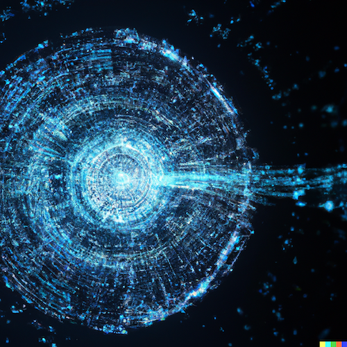
This blog text was 100% human generated but the image was created with OpenAI Dall-E2.
“In order to survive and win in the ever-changing world, keep updating yourself.” – Gordon Moore
Gordon was born during the Great Depression. His dad was the local sheriff. They lived in the small farming and ranching town of Pescadero, California. He was a quiet kid, but he was optimistic and hopeful. He loved the great outdoors and would often go fishing or play at the Pescadero Creekside Barn. He also love science. His parents bought him a chemistry set on Christmas one year which eventually inspired him to pursue a degree in Chemistry. He earned a Bachelor of Science at UC Berkeley and went on to receive his PhD at Caltech.
After college, Gordon joined fellow Caltech alumni and co-inventor of the transistor, William Shockley, at Shockley Semiconductor Laboratory. Unfortunately, things didn’t go well there. Shockley was controlling and erratic as a manager. Gordon and most of the other top scientists left after a year and joined Sherman Fairchild to start a new company. At Fairchild Semiconductor, Gordon and his friend, Robert Noyce, help devise a commercially viable process to miniaturize and combine transistors to form whole circuits on a sliver of silicon. This led to the creation of the first monolithic integrated circuit, the IC.
Gordon and Robert eventually left Fairchild and decided to form their own company. They would focus on integrated circuit development so they named their company, Integrated Electronics. They started making memory chips and focused the company on high speed innovation. The company did extremely well at first but also faced some difficult times that required significant changes. All the while, Gordon focused on pushing things forward and taking risks. They had to constantly reinvent themselves to survive. The company was later renamed to something that you might be familiar with, Intel.
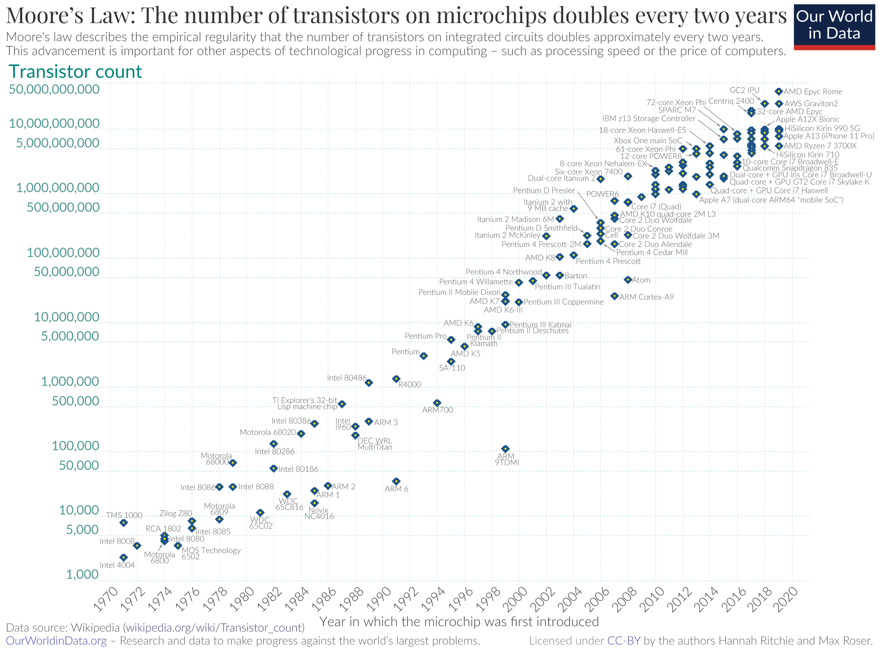
Gordon believed that the key to their success was staying on the cutting edge. That led to the creation of the Intel 4004, the first general purpose programmable processor on the market. Gordon had observed that the number of transistors embedded on the chip seemed to double every year. He projected that trend line out into the future and made a prediction that the number of transistors would double at regular intervals for the foreseeable future. This exponential explosion that Gordon predicted would power the impact, scale and possibilities of computing for the world for years to come. Of course, you know that famous prediction. It was later named after him, “Moore’s Law”.
In 1971, the first Intel 4004 processor held 2,300 transistors. As of this year, the Intel Sapphire Rapids Xeon processor contains over 44 billion. The explosion of capability powered by science continues to accelerate the technology that enhances and amplifies our daily lives. This past Friday, Gordon Moore passed away at his home in Hawaii, but the inspiration, prediction and boundless technical optimism that he started continues to live on.
I know there is a lot going on right now. We are facing uncertainty and considerable change. It can create fear and apprehension. Technology is constantly being disrupted as well as its role, and our roles, in applying it to our businesses. While not comfortable, we need to embrace the change. Lean in and learn. We need to constantly find new ways to reinvent ourselves and what we do. Embrace the exponential possibility of the future! We can do this!
Moore’s Law – By Max Roser, Hannah Ritchie – https://ourworldindata.org/uploads/2020/11/Transistor-Count-over-time.png, CC BY 4.0, https://commons.wikimedia.org/w/index.php?curid=98219918
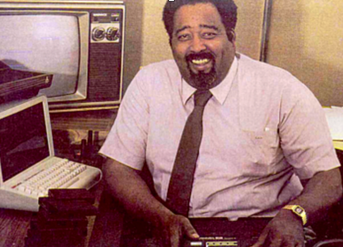
Jerry had a new idea. The coin operated arcade game he had developed in his garage was cutting edge. Instead of using discrete logic hardware that typically drove video arcade games, Jerry decided to use a microprocessor. His microprocessor-driven arcade racing game, called Demolition Derby never made it past field testing to appear in the video arcade scene, but a year later, Gun Fight appeared as the first widely released microprocessor-based arcade video game. What Jerry had developed in his garage became a real game changer. But his biggest contribution was yet to come.
Jerry Lawson was born in New York City. His dad was a dock worker, a longshoreman, who was fascinated with science and along with his wife, always encouraged Jerry’s interest in scientific hobbies, including ham radio, chemistry and electronics. After college, Jerry moved to San Francisco and took a job in the sales division of Fairchild Semiconductor as an engineering consultant. It was there that his garage experiment became a reality. He was promoted to Chief Hardware Engineer and Director of Engineering and Marketing for Fairchild’s video game division. He also became one of the two sole black members of the Homebrew Computer Club, a group of early computer enthusiast that included well-known members, Steve Jobs and Steve Wozniak.
One of the problems with video games at the time was that they were hardcoded to just one game. Home game devices had been created but they were limited to the games you could store in hardware. Jerry knew that the home gaming market could be expanded if they were able to offer a way for consumers to change out the game in a convenient way. He set to work on a new idea. Based on the previous pioneering work he did in moving from complex discrete logic to a software microprocessor-driven design, Jerry knew there had to be a way to make that software portable. He moved the game code to ROM (read only memory) and packaged it into a highly portable cartridge that could be repeatably inserted and removed from the console without damage. This would allow users to purchase a library of games to enjoy, effectively creating a new business and revenue stream for console manufactures and game developers.
Jerry’s invention, the Channel F console (the “F” stood for Fun) included many pioneering features. It was the first home system to use a microprocessor, the first to include a detachable joystick, the first to give users a “pause” button and of course, the first to have swappable ROM cartridge-based games. Sadly, the console was not successful, but the invention changed the home gaming world forever. A year later, a gaming console came to market using Jerry’s revolutionary concepts, and took over the world, the Atari 2600. Many other game consoles followed with the explosion of games and options for the consumer.
Jerry changed the industry! Despite his two game changing products being market failures, his ideas lived on and created a new industry. He is now recognized, honored and celebrated as the “creator of the modern video game console”.
I don’t know about you, but Jerry and his story inspired me. I see brilliant minds all around us. They dream into the future and even implement pioneering work that changes the game. Sadly, many go unnoticed until they are gone. Jerry’s story reminds us that we should applaud these pioneers. They help nudge technology and our human experience forward. We should celebrate them, acknowledge them and honor them. I know some of you are pioneers too. Keep innovating, dreaming, creating, building and inspiring! We need the game changers!
“We keep moving forward, opening up new doors and doing new things, because we’re curious … and curiosity keeps leading us down new paths.” – Walt Disney
I love Disneyland! My girls and I just concluded a three day visit at Disneyland and Disney California Adventure. We stayed on property so we could enter the park early in the morning and enjoy the cool awakening of this magical place. Despite having fully memorized the layout over the past nearly 17 years, my girls still love to pick up a map. They are not alone. I saw many families around us walking down Main Street with their heads buried in a map including the digital version on their smartphones. I love watching our guests, especially the little ones at the beginning of the day when they are full of anticipation and energy. Their little arms struggle to stretch out the map in front of them as they bounce with excitement. It’s contagious! As they scan the map, their eyes tell a story of the wonders, adventures and discoveries that await them. There is something powerful about exploring new possibilities, mysteries and experiences. You can feel it too, can’t you?
We are curious creatures. It begins early as we try new things. Sights, sounds, smells, textures. They all fascinate us and pull us like a gravity to explore more. We ask, “What is this? How does it work? Why is it here? Is there more to this?” We peer into the small, the quantum world, asking if it can be even smaller. We gaze into the heavens and ask how far does it go and is it even bigger. Our insatiable curiosity launches discovery, plunging to the depths of the sea and flying to the surface of other worlds. Our eyes are hungry for discovery and our minds are thirsty for excursions. We map our menu of options and begin to explore.
This past week, NASA’s Webb Space Telescope rocked the world with new discoveries of the universe that we have never seen before. Thousands of new galaxies, solar systems, exoplanets and star formations from 290 million light-years away were suddenly made available just inches from our eyes. Each discovery reminds us that we are part of something even bigger. It opens up a new map to explore. Before us, the universe. Where should we go next? What is this? How does it all work? Why is it here? Is there more to this? And on we go. We keep exploring because we are curious.
What fascinates you? What are you exploring today? Stay curious!
Net Energy Metering (NEM) allows homeowners who generate their power with solar panels to serve their energy needs and receive a financial credit on their electric bills for any surplus energy they feed back to their utility. In California, the NEM tariff is set by the Public Utilities Commision (PUC). In recent years, they have been contemplating changes that have create quite a stir by Solar owners. Utility companies, Pacific Gas and Electric (PG&E), Southern California Edison (SCE), and San Diego Gas & Electric (SDG&E) are requesting a change to cover the cost of operating the grid. Solar owers argue that the proposed changes would discourage solar energy and place a hefty tax on their Solar systems.
For my family, Solar was an investment we could make to help us transition us to a more green energy future. We computed our ROI along those lines with the expectation that incentives, especially net metering, could disappear soon. I fully admit that the Federal Investment Tax Credit (ITC) of 26% made it easier to justify but I know the utility based incentives may not be sustained forever.
The Problem with Residential Solar
It is easy to focus on the power rates for electricity but we often forget that there are capital and ongoing costs to run the grid infrastructure. This is true even if you rarely use the grid power. Regardless of your view of the utility companies involved, the truth is that there is capital and operational expense for us to have the luxury of pulling power from the grid when solar production is not enough to charge batteries or support our homes. If we are not paying that, those costs are getting distributed unfairly to non-solar customers. Studies show that this is typically lower income families who can’t afford solar installation fees.
However, the NEM v3 proposed $8 per kW of installed Solar generation per month may be a viable approach, but it does seem too high. We sized our solar panels to cover our needs at 8.5kW. The additional $68/mo connection fee isn’t terrible but also isn’t much less than our electric bill without solar at $120/mo (usage not taxes). With cloudy days, pulling from grid could easily make the bill as much as or higher than before solar. There should be a fee, but it needs to be reasonable.
Solar Voltage Rise
Another problem with residential solar is the challenge of residential voltage rise. This is caused by the NEM ability to “sell back” power to the utility company. To push excess solar generated power back to the grid, the solar system must raise the voltage slightly higher than the grid voltage. This is generally fine as there is demand on the local grid for that power. However, as more and more homes in the neighbor add solar, all of those solar systems are trying to push their excess power back to the grid at the same time (morning to early afternoon during the sun’s brightest). As each system bumps the voltage to push the power onto the grid, you start to see the local grid voltage rise. I have seen nominal 220v jump to 224v in our area. At some point that voltage becomes too high and electronic equipment will start to fail. I’m sure the utility company has ways to deal with this, including sending frequency changes to signal solar inverters to stop production, but this would be added investment for them to accommodate solar.
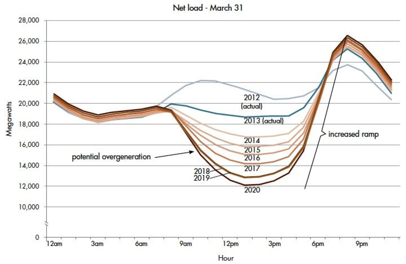
Solar Duck Curve
Even if solar voltage rise is managed, there is another problem. When the sun is out, the utility generation demand can drop significantly but then surges when the sun goes down. 4pm to 9pm happens to be the time of the greatest demand. It coincides with evening meal preparation, additional lighting and afterwork entertainment demands. This means that the demand pattern has changed and has created a challenge for utility companies to support. If you look at the demand curve before solar, it looked like a camel’s back, but now the “solar production” dip is so dramatic that it forms a massive and steep jump in the evening. That is difficult for the grid and for power generation to match. The new demand graph is called the solar duck curve due to the new shape (see https://www.energy.gov/eere/articles/confronting-duck-curve-how-address-over-generation-solar-energy).
Solar rise and the duck curve demand are caused by solar systems that can “sell back” their excess power. The solution is to have the excess power stored locally through energy storage devices (ESDs), basically, batteries like the Tesla Powerwall or similar solutions by Enphase or LG. That allows homes to switch to battery power in the afternoon and through the evening (especially 4pm-9pm when energy demand is highest). With local storage, the solar rise and the duck curve issues are mitigated. The problem is that except for the luxury of having whole-house power backup during power outages, there is no incentive to get an ESD to help shave the peak demands. A good approach by PUC could be to discourage “selling back” power to the utility company (especially during peak demand) and instead, encourage adding ESDs to storage the over production for later use.
Residential Solar Advantages
There are good advantages of residential solar. While I highlighted the downsides, I would be remiss not to point out some of the advantages that are not tied to financial benefit to the owner. For one, the distribution of power generation, putting it closer to the edge where the demand is being generated (homes), can help relieve the constantly growing demand on the electrical grid system. With ESDs, we can reduce the load on the grid which often must transmit power over greater distances to meet the rising demand loads. Local production of power helps.
Another benefit to local home generation is the greater awareness by homeowner of their energy footprint. By having a home based solar system with a battery (ESD) and easy tools to monitor usage, the the homeowner becomes very conscious of how much energy is being used, and wasted. We began to optimize our usage of devices to reduce the demand or align it to the time when we have the most energy production. It is a game and I know this can be subjective but it is also a powerful learning opportunity that I believe can help us optimize for a greener future.
Conclusion
We need to encourage renewable energy generation and storage at the edge, where it is being used. At the same time we need to ensure funding for a resilient power grid without placing undue burden on lower income families. There are other renewable energy options, but I also believe we should exploit the fusion power that shows up each day in our sky (our local sun), as much as possible. It’s incredible how much power is available to us every day in the sky and our technology is just beginning to tap it. More efficient solar cells and higher capacity batteries are on the horizon (no pun intended). The future of sustainable and environmentally friendly energy is bright, we just need the courage to pursue it.
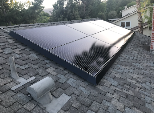
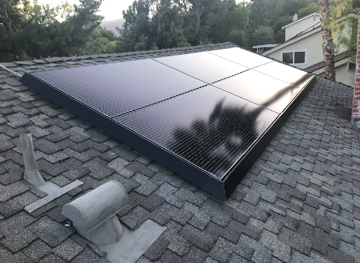
After research and talking with several solar companies, we decided on an 8.5kW Tesla Solar plus Powerwall+ system with their new high efficiency 425W panels. The main reason for our decision was the low cost, handsomely framed panels and the whole house backup capability. Other solar companies had good backups systems but we did not find any who would provide whole house backup. And, more importantly, we were delightfully surprised to see that Tesla came in with the best price. Having said that, we would soon discover that they seemed to have significantly reduced overhead by mostly eliminating customer service.
The Install
25 September 2021
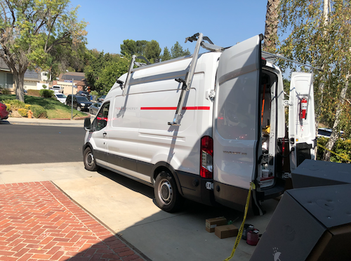
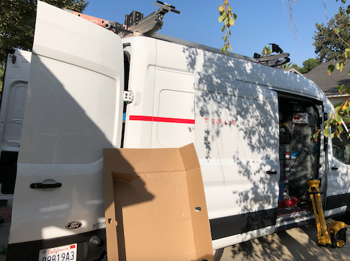
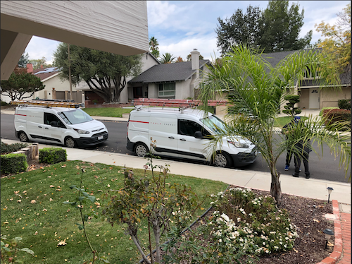
Tesla Crew
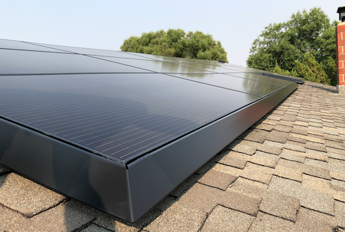
After ordering, reviewing designs, applying for HOA and City approval, we were finally ready to get the system installed. Two different crews arrived over a span of a week to get the system installed. The panels went on first. The panel install crew was professional and friendly. However, when they left I noticed that the handsome skirts (frames) we were so excited about were only installed on the front of the house (street facing roof). It looked great but I had expected to get them on the back as well. I reported it and in just a few days a technician came out and added the skirts to the back roof panels. He explained that they usually only install the skirts on the front. So, please note, if you want skirts on all your panels, make sure you let them know in advance. Also, the skirts are only put on the left, right and bottom. There are no skirts on the top to allow heat to escape from the panels during the hot summer.
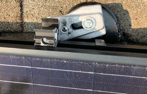
Panel Mount – Torx T30
While installing the skirts for the back, I noticed one of the panel edges was sticking up about 1/2″ higher than the rest. The technician tried to fix it but he didn’t have all the tools. He only had what was needed to install the skirts. He asked me if I had a Torx T30 driver. I didn’t but he explained how I could adjust the panels myself. I picked up a T30 at our Newhall True Value store. I climbed up on the roof and found the adjustment area. I used a vice grip on the screwdriver to get enough leverage (mostly because I’m pretty weak especially when I’m up on the roof). I was able to lower the panel 1/2″ so it was flush. It looked beautiful.
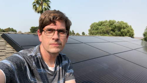
FrontBack
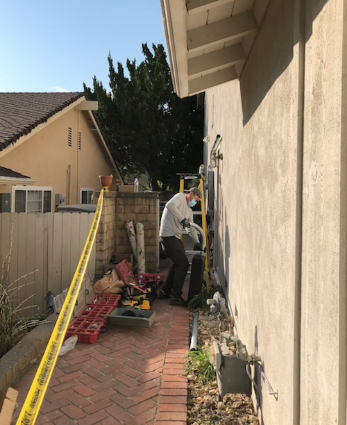
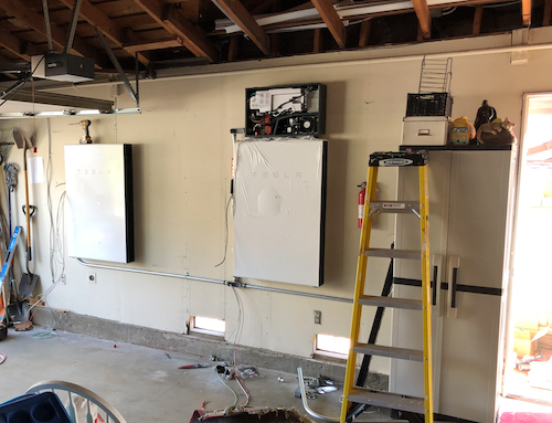
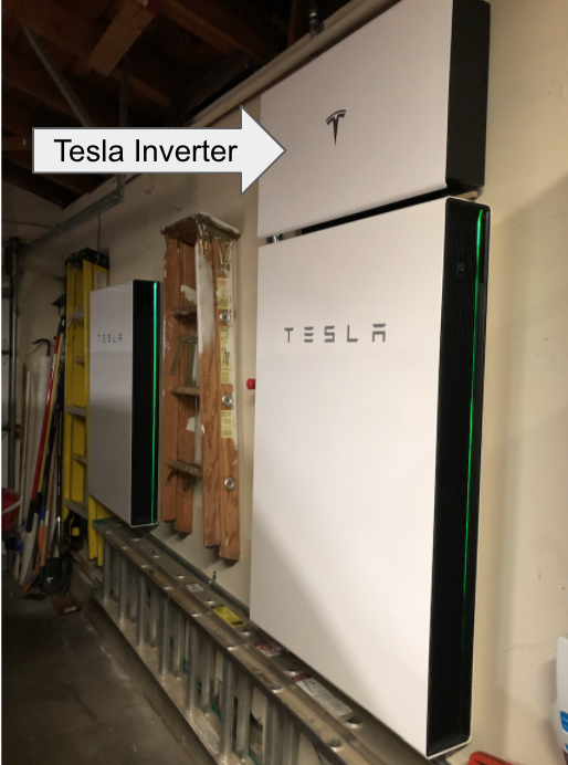
A week later, another crew showed up to wire it in and commission the system. This meant a day without power, but we were prepared for that. I tried not to be a nuisance, but couldn’t help but watch and ask questions. I made sure all of the crew had plenty of bottled water, Gatorade and snacks, including ice cream candy bars since it was so hot. They installed the Powerwalls in our garage and wired in the breaker panels and Tesla Gateway by the utility meter. After everything was installed, they powered it up and began the commissioning process.
The Problem
During commissioning, the first signs of trouble started showing up. The installers downloaded the latest software updates but were unable to get the Solar Panels to work correctly. The solar assembly was only producing 160W in full sun which doesn’t even show up in the app. They tried for hours, upgrading, rebooting, calling. They eventually gave up after showing me that the Powerwall could power our house if they cut the mains (based on 22% charge from the factory). They explained that Tesla would send out a software patch to fix the Solar panels, most likely.
I contacted our Tesla Advisor to report the problem and to see if they had an update. After several days of emailing, texting and calling, I received a note from the advisor that our inspection would be scheduled in 3-4 weeks and he would contact the electrician about the problem. I spent another week requesting updates but my Advisor had gone radio silent. It turns out that this is a common experience with Tesla. Assuming best intentions, I can only imagine that the advisors are understaffed and overwhelmed. Regardless, it all results in a very frustrating experience for the customer.
I did manage to finally get an update and a promise to further investigate the issue. While I waited, I decided to do some more research on the system to see if I could find the problem myself…
HIGH VOLTAGE WARNING: I need to stop here and remind everyone that these systems contain extremely high voltages and are dangerous. Hopefully it goes without saying, but please be careful if you poke around inside these electrical boxes. High voltage can be fatal.
The Investigation
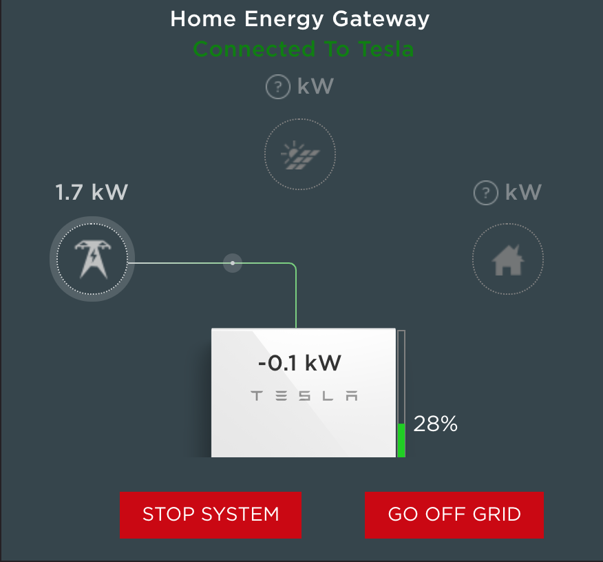
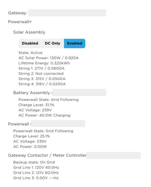
You can connect to the Tesla Gateway by scanning the QR code inside the box. It will have your phone connect to the Gateway’s access point. You will need to stay close to the gateway if you connect this way (and browse to https://192.168.91.1). However, keep in mind that it is also connected to your home network and if you know how to find the IP address, you can point your browser to that IP and login as the Installer to see more details about the system. Your browser will likely require that you ignore the security certificate warning (more on this in the observations section below) and you will need to toggle the power switch to one of your Powerwalls but it will let you in. That is essentially their 2nd factor system to ensure you are authorized. Here is what my system looked like after installation on the main screen and on the “System” screen :
The System screen also shows details about the solar generation, Powerwalls and power usage:
Below the above list was a section for “Remote Meter” that would occasionally appear. This was particularly interesting:
Remote Meter (Vxxxxxxxxxxxxxxx) CT 1 (Solar): —W
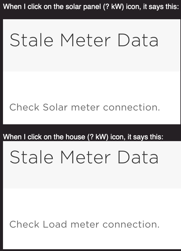
That seemed odd. Also when I clicked on the solar panel icon on the main screen, it would say “Stale Meter Data” – that had me wondering if the solar meter was the real issue.
The Fix?
I first disabled the Solar Assembly by clicking “Disable” on the System screen.
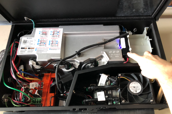
I opened up the Inverter, the box above the first Powerall. There is a small latch on the bottom that will unlock and let the panel swing up. I found a wooden dowel to prop it open so it would bang on my head the whole time I was investigating.
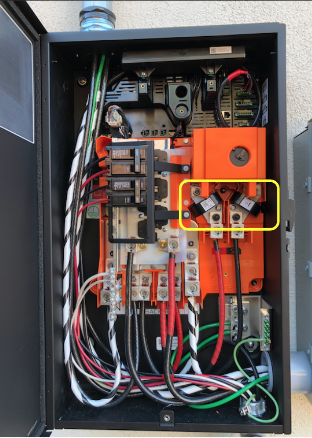
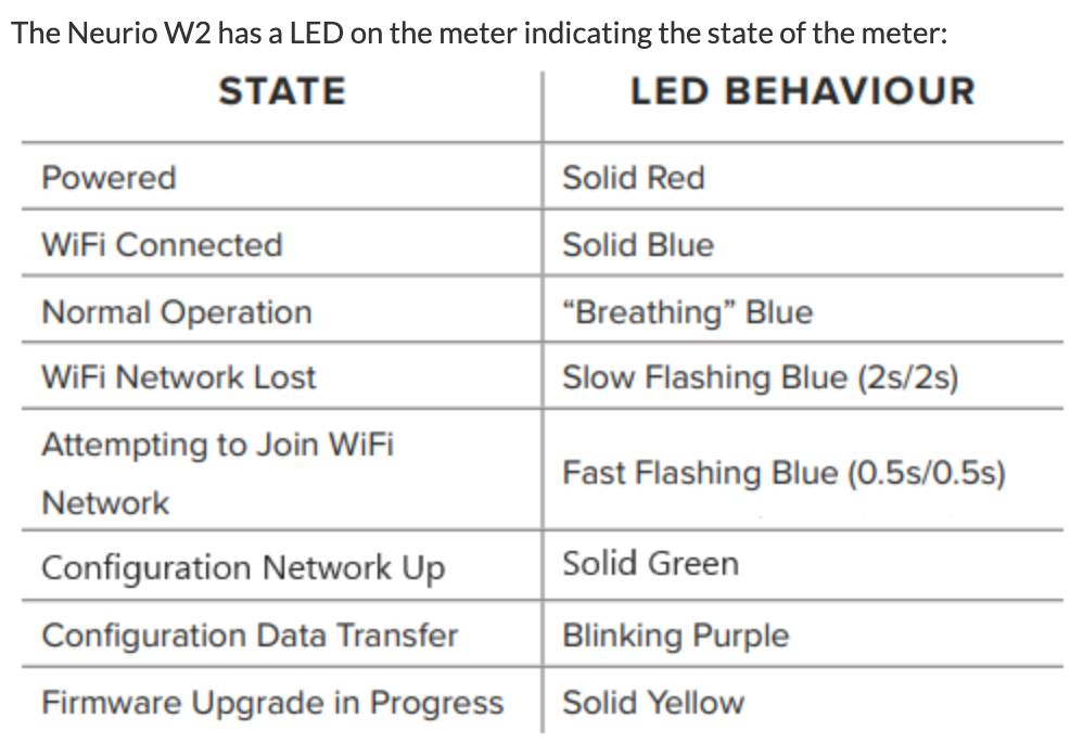
I noticed that there was a box on the right that had a “n” LED flashing. The code on the box was the same code that was listed as the “Remote meter” in the system’s display (the one showing no power). Some more research and I discovered that this module is a Neurio W2-Tesla WiFi based current reader that sends the solar power data to the Gateway.
Neurio was recently purchased by Generac but you can still find manuals and some models for sale online. This particular model, W2, has been customized for Tesla. It is designed to connect to the access point of the Tesla Gateway and send the solar power data.
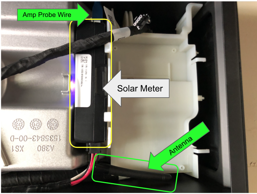
CT-1 Amp Probe Wire
The Neurio has a wire plugged in to the top in the CT-1 (current transformer) port. I traced it over to the solar inverter where a clamp is wrapped around the solar inverter output AC line to measure the amperage. I re-seated that connector.
Antenna
I then noticed that there was an antenna jammed below it that was tucked to the left, under the massive metal inverter shield. I turned the antenna to the right, in the open unshield space.
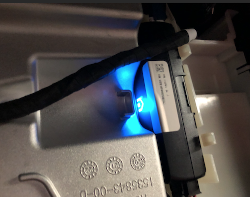
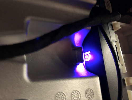
As soon as I did these two things, the LED “n” on the box began to change and a tune started coming out of the box. It sounded like “I am connected now”. The flashing “n” became a solid blue light.
Eureka!
I went back to the System screen and re-activated the Solar Assembly by clicking “Enabled”. This takes several minutes and you will see the system go through and activate the solar arrays, test relays and impedance before the assembly comes online.
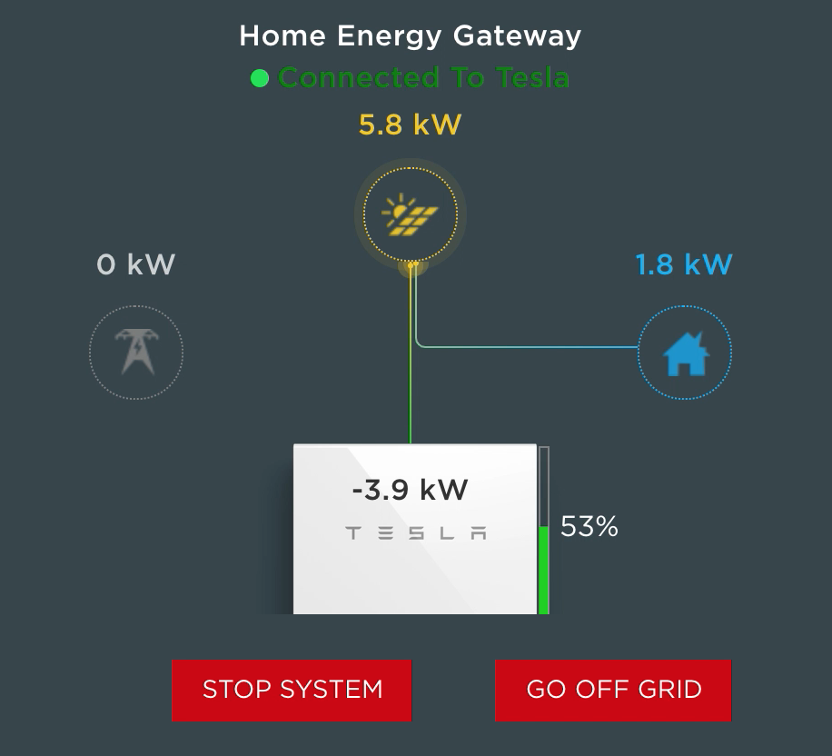
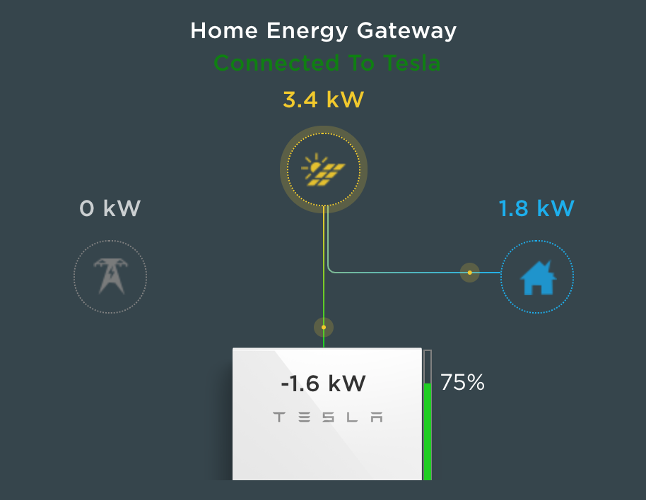
As soon as the Solar Assembly came online, I started seeing kW of power show up on the Systems screen. 5800W of power was coming in, fully powering the house and charging the Powerwalls!
Not so fast…
Sadly, just two hours later my elation was destroyed. The solar energy dropped back to zero.
I checked the inverter. Sure enough, the Neurio was flashing again. I attempt the above process again, several times, but no joy this time. It would chime and go green, but then started flashing again. Based on my research, the Neurio connects to the Tesla Gateway WiFi only. The beeps and flashes indicate that it is unable to connect to the Gateway WiFi.
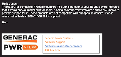
One thought I had was to reach out to Neurio (which is now owned by Generac) to see if they could provide the API, pinout or schematics for the W2 device so I could troubleshoot at the firmware and component level. When I contacted them, Generac replied that the serial number for my device contains proprietary firmware by Tesla that they cannot support. They recommend that I contact Tesla at: 888-518-3752. Oh well, it was worth a shot.
The Workaround
I love a challenge. In fact, when something isn’t working, it is almost an addiction to me. I have to figure it out and fix it! So, I had two thoughts at this point. First, I wanted to see what the Neurio was actually doing. I thought about setting up an ESP8266 to be an WiFi access point to intercept the Neurio’s communication attempts with the Gateway. But before I do that, it occured to me, I wonder what would happen if the system didn’t have a solar meter at all. In my investigation, I discovered that the solar power meter feature is often an add-on or post-install enhancement. Maybe this was more of an add-on feature than a requirement?
At the minimum, I wanted to see if there are alternatives to the Neurio in the Tesla configuration. Unfortunately, there isn’t an easy way to edit this data. I discovered that settings could only be set during the initial setup time. That would require running the setup wizard again. I decided to be bold and fire up the installation Wizard. At the bottom of the system portal is the “Run Wizard” link. Of course, I clicked it.
WARNING: I’m fairly confident that you can completely break your Tesla Solar setup using the Wizard, maybe even disable power to your house permanently. It is intended for installers. I’m taking the risk, but you should consider this first and be cautious about proceeding. I’m also fairly confident I’m going to void something in the process, but if you put something in my house, fair game, I must hack.
The wizard is straightforward. It requires you to Stop the system, but the settings are mostly intuitive. When I arrived at the Meter screen, it had 3 different meters displayed. I apologize, I did not take screenshots but will update this blog if I capture them in the future but the screens are very basic.
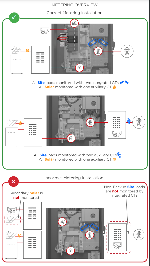
Two of the sensors were for the built-in CT’s used to measure the power in the Tesla Backup Gateway (you can see them on the main bus if you open the Gateway panel – which I did).
Tesla Backup Gateway DANGER: High voltage – Seriously!
These tested extremely fast (subsecond) were working correctly and tested “good”. The third meter, a WiFi meter, was the Solar Meter (Neurio) and it’s status was Error, unable to connect. I clicked the connect button which reported it would take 3 minutes to configure the WiFi sensor. No shock, it didn’t work. I tried it 3 more times. The “Advanced” drop down allows you to add MAC address and IP, but this didn’t help. There was a “Delete” button. I thought it might be worth a try to delete and re-add. At the bottom were options to add “WiFi” or “Wired” CTs. I tried to add the Neurio (WiFi) again, multiple times, rebooting the Neurio occasionally to see if that would help. Nothing.
Here is where something interesting happened. The Wizard would NOT let me advance because the WiFi sensor was not healthy (connected). Hum… Well, I figured I would just have to delete it to see what other screens I could find in the Wizard. I deleted the Neurio. I advanced to the next screen and was presented with a “Warning – you do not have a solar sensor selected.” Naturally, I ignored that and continued.
Commissioned! I completed the Wizard setup and the system came back online. Surprisingly, the system screen looked basically the same but the dynamic flow diagram was actually working. There were no sensor errors or warnings. Power was flowing from the Grid to the House. It was the middle of the night so I signed off and went to bed.
I know what you are thinking. This is dangerous, right? I mean, we seemed to have removed solar power observability from the platform. Will the Gateway and Inverter sill know what to do? Well, it turns out… it does!
The Power of the Sun
Next morning, I woke to discover solar generation was charging the powerwalls and our house was completely powered by the sun! I still want Telsa to fix the Neurio or, better yet, provide some hardwire CT to monitor Solar power generation. I’m assuming that the display below means that the Gateway is computing the the solar generation based on other CTs. In any case, my workaround is in place and we now have a working system again.
As I’m looking at my phone, I realize… I’m holding the power of the sun in the palm of my hand. Yes, that is a geeky Doc Ock reference. We are now powering our home with an ancient but reliable and self-regulating, thermonuclear fusion reactor… our sun.
The Return of Tesla
1 November 2021
I gave up on waiting on Tesla to respond to me about the Neurio. I figured it didn’t matter since I had a working system. A month after the install and I still didn’t have an inspection date. Then it happened. I received a text message and email from Tesla that my inspection was scheduled. There was NO DATE or TIME given. Instead of asking, I figured it didn’t matter. We would see what would happen.
The day of inspection had arrived. A surprise knock on the door and there was Ishmael from Tesla. He explained he was there to meet with the City inspector for the final inspection. I showed him the gear, the Powerwalls, the gateway and the breaker panels. He looked at me and asked, “Did the install crew not put on the warning labels?” Nope.
This was something I had noticed after the installers left. In the Tesla plans are specific instructions on where to place the red warning labels on all of the gear. It includes a helpful diagram for anyone wanting to know how to kill all power in case of emergency. I had raised this issue with my project advisor a few times, but as usual, told me he would look into it and of course, nothing happened. I explained this to Ishmael who rolled his eyes and expressed apologies and said he would need to call to get the labels or it would not pass inspection. He would wait for the delivery and get them installed and ready for the City.
Shortly after meeting Ishmael, another Tesla vehicle pulled up. I figured it was the inspection stickers, but instead, it was Rocío, a Quality Assurance technician. She told me that her job was to make sure everything was installed correctly and running. I almost hugged her! I expressed my delight and appreciation that she would check on us. I explained everything that happened including how the installers said it must have been a Tesla software bug and gave up after trying for hours to get it work. I also told her about the Neurio hack I had done to get it working. She was shocked, sympathetic and determined to fix the issue.
Naturally, Rocío attempted to reset the Neurio and discovered the same thing that I did, with the exception that she was able to get the Neurio to work if she held the connector, pressing on it in a certain way. “There is clearly something wrong with the hardware and it needs to be replaced,” she concluded. I hate to be cynical, but I was definitely thinking this new chapter in my Tesla adventure would turn into an multi-week RMA, repair order and a return visit that may get scheduled sometime next year, if I’m lucky.
To my delight, Rocío looked straight at me and said, “And we’re going to get this fixed today!” She was right! She made a phone call and 30 minutes later another Tesla van showed up with the replacement Neurio!
Rocío got it working. Less than 30 minutes later she had the entire system back online and working correctly. “That’s amazing!” I told her. She clearly saw my astonishment and said, “I used to be an installer, I know what’s needed.” Well, that was completely accurate. She didn’t stop there. She examined all the gear and climbed up on the roof to ensure all the panels were in good order.
Shortly after the good news, the warning labels arrived and were attached to the new gear, ready for the official inspection. I started passing out my sincere appreciation, candy bars, water and Gatorade to these brilliant Tesla soldiers that had come to save the day. After bidding farewell to our new friends, Rocío drove off on her shiney white stallion… uh, I mean Tesla van.
About 30 minutes later, the City Inspector arrived and after a quick survey of the installed gear with Ishmael, signed his approval. Now we are on to the Permission to Operate (PTO) by Southern California Edison.
Power Gremlins
3 November 2021
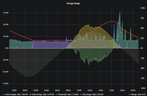
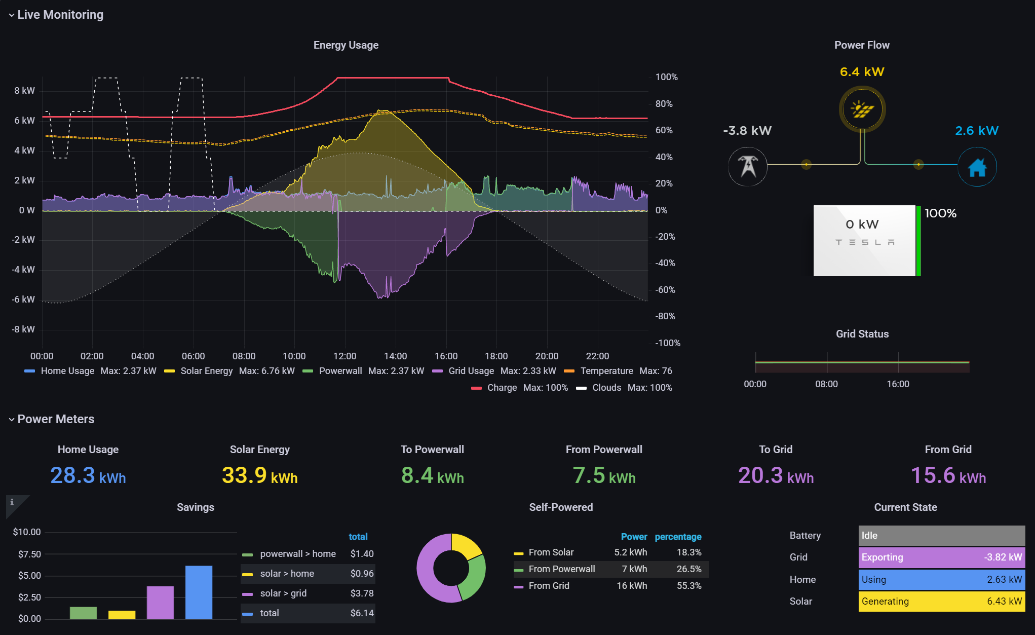
I should definitely learn to be more guarded in my optimism about this Tesla adventure. After two days of having the new Neurio re-installed, I started noticing something odd. After solar production when I would expect the Powerwalls to kick in and power the house, I would see grid power start to show up and the Powerwalls drop to zero. It would only last for a few minutes then return to normal operations. Looked at the Powerwall Dashboard I set up and can even see the grid power spiking during the day when solar production was more than enough to power the house.
Powerwall Dashboard: Notice the purple (grid power) spikes throughout the day. These just started showing up after the new Neurio was installed.
The grid power spikes did not exist before the new Neurio. I went out to look at the inverter. The Neurio’s purple light was mostly solid but would “flicker” blue. It was random, like a candle flame not like the error condition of the previous Neurio. It was happening constantly as I watched. When the flickering would get bad, I would see the powerwall drop to zero and grid power surge. There seemed to be a correlation. At any rate, I wasn’t going to let the flickering continue.
HIGH VOLTAGE WARNING: I need to stop here again and remind everyone that these systems contain extremely high voltages and are dangerous. Hopefully it goes without saying, but please be careful if you poke around inside these electrical boxes. High voltage can be fatal.
I powered off the Neurio by unplugging the power next to the antenna at the bottom. I noticed the antenna was once again tucked under the massive shield. I guess that was the typical install. I changed it so it was pointing away from the inverter shield and reworked the cables to plug it back in. The Neurio went through the startup (flashing, then solid green, then blue and then purple). I watched it for a while and noticed it stayed solid purple, no flickering.
I don’t know if this was a fix or a sign of things to come. Other people have reported similar problems with the Neurio, including a YouTube video on how to reset it the way I did. It is rather shocking how unreliable this little box is. I understand it is a “revenue grade” meter which is likely why Tesla is using it, allowing them to report “Solar Renewable Energy Credits” (SRECs). The Inverter itself seems to have a decent meter without the Neurio which is why my workaround hack worked while waiting for the Neurio replacement. If the reset doesn’t work, I will likely revisit my “fix.”
5 January 2022
The “fix” was temporary. It appears to be a resource leak that requires the Neurio to be restarted. The good news is that Tesla finally recognized the instability and sent out a 21.44 firmware update that fixed the Powerwall from disabling solar when the Neurio goes into a bad state. Finally! I was planning on ripping the Neurio out after PTO, but now I don’t have to do that. I’m currently on firmware 21.44.1 and just heard from the community that others are seeing an upgrade to 22.1 that also upgrades the Neurio from firmware “1.6.1-Tesla” to “1.7.1-Tesla” (you have to access the vitals API and decode the protobuf binary payload to see this – see here). Hopefully that helps with stability.
Permission to Operate
2 February 2022
PTO, finally! Our utility company, Southern California Edison (SCE) granted permission to operate. It took Tesla several tries to get the PTO request submitted correctly. SCE was notifying us of all the transactions but we were not able to see the full application or help. Believe me, I tried! In any case, our installation adventure has finally come to an end. It has been seven months since we started this epic journey. It is good to finally have a fully operational system.
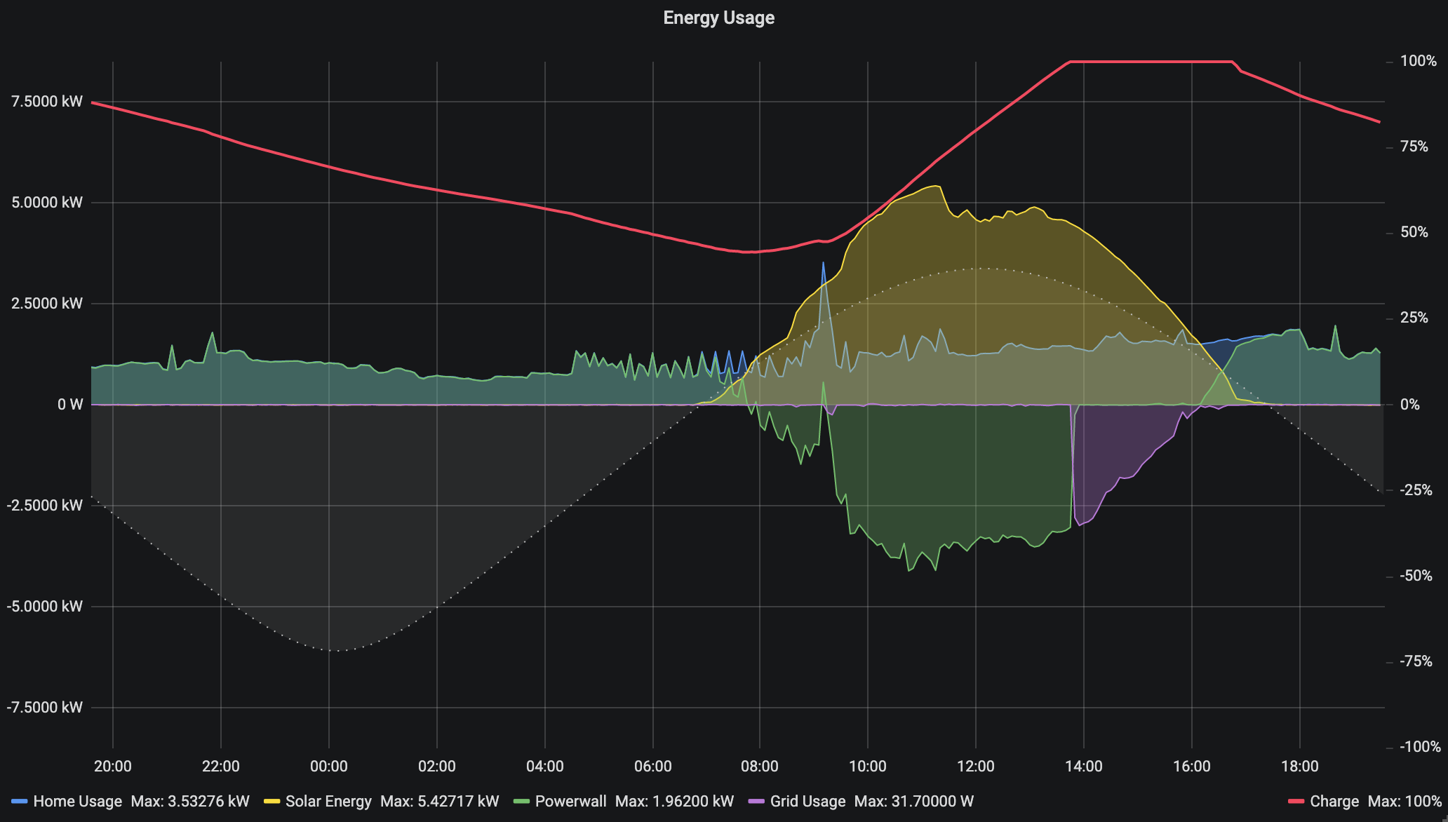
To be fair, we have had a working solar system with Powerwall backup since October, but without PTO. PTO means that our system is no longer in self-consumption test mode. We can now push excess solar production to the grid for a credit. For the first time ever, we see grid graph going negative!
24 hour graph of energy usage including Powerwall (green) charging and pushing to the grid (purple).
Conclusion
The Tesla Solar system has been an adventure for us. I don’t regret going with Tesla even though they have improvement areas, especially related to consumer experience. We love the look of the panels and the equipment. In typical Tesla fashion, the design is stunning and feels like quality. If you do select Tesla Solar, my advice is to plan on being the project manager. Stay on top of the details to keep things moving and make sure items are not dropped.
Regardless of who you go with, I recommend you set some non-negotiables to help you filter. Here were my non-negotiables:
Aesthetics – We wanted something that looked high-tech, neat, clean and symmetrical on our roof. I wanted the dark panels (no white lines) with a clean looking frame.
Whole House Backup – We wanted batteries capable of running our house over 24 hours in the event of a power outage and a system that would charge the batteries during the day even if power was out for extended days.
Home Automation and Monitoring APIs – I wanted a system I could hack, use tools to monitor, dashboard, trend and even make decision on home automation components to optimize our energy usage.
Off the Grid – We wanted the system sized to allow us to be self sustaining with no need to use the grid even at night, fully expecting that at some point Net Energy Metering disappears or becomes less attractive, the system will still provide us with a zero grid usage option.
This helped considerably. It eliminated the list down to a handful and the lowest cost on our list was Tesla, who also had the best aesthetics IMHO. Now to be clear, as I mentioned above, Tesla is seeing explosive demand for their option and their customer service struggles a lot. I also had the opportunity to work with several incredible Tesla technicians who helped us.
I am extremely happy with our Tesla system and would recommend it to anyone, despite the bumps along the way. Tesla hit on all my non-negotiables and is elegant, fun and powerful. It has become a delightful hobby as well as a powerful utility for our green energy mission.
While a similar adventure may not be for everyone, if you are in the market for a Solar system, I still highly recommend checking out Tesla’s options. Use this link and you can save $300 if you do order and I get a reward too: http://ts.la/jason50054
I have to confess. I love toys. To me, this new Tesla Powerwall+ Energy systems is a gigantic (and expensive) toy. I have thoroughly enjoyed tinkering with the system and building electronic accessories and software to manage it. As you have seen in this post, I wrote my own python API library (pyPowerwall) and created a Powerwall Dashboard to better see what the system is doing over time (credit to other open source projects I mention below).
One thing that the Tesla is missing is a good instrument panel display. Sure, you can run the app all the time, but I wanted something that would show the solar production and other details like a physical dashboard but without opening an app. I built one. It is hanging next to the Powerwalls in our garage. Much to my wife’s initial trepidation, I also built one and hung it in our kitchen. It turns out that I’m not the only one to appreciate it… well, after a while anyway. 🙂
Here are some of my toys that I gladly share with you. Please reach out and let me know if you find these useful:
pyPowerwall Dashboard with String Data
PowerwallWeb Dashboard – The Tesla App and web based portal present great animations showing the solar generation and usage. However, the information is very limited and not design for visualizing the energy data in multiple ways. I wanted to see a year at a glance as well as the string data (how much power each group of solar panels on the roof are producing). I found this Grafana based dashboard and made some minor changes including the addition of my own python based Powerwall API Proxy. Here is a simple python API module pyPowerwall to pull data from the Powerwall Gateway using your “customer” credentials: https://github.com/jasonacox/pypowerwall. If you are wanting your own Powerwall Dashboard, it is fairly easy to set up with the instructions here using Docker Compose: https://github.com/jasonacox/Powerwall-Dashboard#powerwall-dashboard
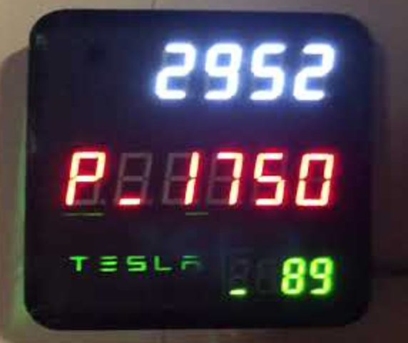
Powerwall Digital Display
Powerwall Wall Mounted Display – I really wanted to see the current solar generation and state of the Powerwall on a simple LED digital display. I 3D printed a Tesla themed case and installed the displays to show solar, house, battery, and grid power data. The display show the solar production power at the top. House, Powerwall and Grid power data rotate through the middle display and the battery level of the Powerwalls is at the bottom (89% in this picture). You can see a video of the display running below.
The display uses a WiFi enabled systems-on-chip (SoC) ESP8266 WeMos controller and three simple TM1637 7-segment LED display modules. Naturally I used my own Arduino API library (TM1637TinyDisplay) for those and the pyPowerwall proxy to display the results. It would have been nice if Tesla had built a wall monitor to show vitals like this. I’m sure it would have been a nice animated OLED display of some sorts. But this was fun. I needed to build another toy and I love my retro-LED display. If you want to build your own, I have open sourced the design and code and uploaded here for you to use: https://github.com/jasonacox/Powerwall-Display
I took note of several areas of concern and improvement during my investigation and problem solving. I have recorded them here.
WPA TKIP Command Access Point – The Tesla Gateway uses this weaker method to host its WiFi access point. As I discovered the Neurio uses this same access point to send Solar Power data (if it works). WPA TKIP has been dropped due for security reasons and more modern access points use WPA2 and AES encryption (WPA2-AES).
HTTPS Security Certificate – The HTTPS certificate the Gateway uses will create a browser warning (or error) when you go to the system control portal, either via your home network or via the access point at https://192.168.91.1.
Second Factor – For setup, the user is required to toggle the switch on a Powerwall as a 2nd factor to prove authorization, which is a good thing. That works well for me since my Powerwalls are locked in my garage, but if your Powerwalls are outside next to the Gateway, an attacker on-location could easily join and toggle without you even knowing.
IoT Sensors – The main problem on my system was the Neurio W2 WiFi based sensor. This IoT device sends back power data it measure to the Gateway controller. Generally, this is an elegant way to handle transmitting sensor data between systems without having to wire things. The irony is that the Gateway and Inverter already have several wires and control signal between them. Why not add another wire and avoid any WiFi communication outages? Hopefully I will be able to replace my Neurio with a wired solution.
Solar System Plan – I asked the Tesla Advisor to provide me with the design plans developed for the City Permit. They do not provide this without asking. I am glad I asked. The plans have all the schematics for the wiring as well as the layout. I discovered several things that I wanted changed and was able to get them to update before they came onsite. If you wait until they come onsite, they may not have the materials to make the adjustment and, worse, could charge you for any changes.
I found the following github projects, references and diagrams during my investigation into my Tesla Solar Adventure. I’m pasting them all here to be helpful for anyone else experiencing the same problems. The information may not be directly related but could provide a clue.
The famous Greek mathematician, physicist and astronomer, Archimedes had been given the task to verify that the king’s crown was made of pure gold. The king suspected the goldsmith had somehow cheated him, perhaps by mixing in a cheaper metal like silver. But he had no way of proving that so he asked Archimedes to figure it out. One day Archimedes was contemplating this problem while taking a bath. He happened to notice how the water was being displaced as he stepped into the full tub, spilling out all over the floor. He remembered that silver weighs less than gold by volume. It suddenly dawned on him that if he were to take the same amount of pure gold by weight as the crown, and put it into water, it should displace (spill) the same amount as the crown. Archimedes was so thrilled with this discovery that he immediately hopped out of the bath and ran to tell the king, exclaiming “Eureka!” which means, “I found it!”. In case you are curious, when Archimedes tested the crown, he discovered that it displaced more water than gold, indicating it was less dense (not pure gold). So, indeed the king had been cheated by the goldsmith. You can probably guess what happened to the goldsmith!
Learning is hard. There really isn’t a way around it. If you want to learn something, it’s going to take effort. I often use the excuse that the human brain is optimized to save energy. We build models and synaptic connections to do things “without conscious thinking.” We process huge amount of sensory data every day. We are faced with a plethora of problems we need to solve. It would be overwhelming if it wasn’t for these optimized unconscious neural pathways that allow us to sort, react and perform our tasks without much thought.
Learning builds more capability. At some point in our past, we learned something new and, Eureka! That learning was forged in our brains. It allowed us to perform our duties while we engage our higher brain functions for more important tasks like daydreaming, pondering the next season of Loki, or wondering what’s for dinner. Ok, so maybe those aren’t more important tasks, but you get the idea. By leveraging our learning, we expand our capacity to respond well to incoming tasks, difficult challenges, complex changes and even enjoyable exercises.
Learning builds on learning. I know that sounds a bit meta, but if you examine your own experience, you know that learning builds pathways to future learning. I remember the first time I learned to program a computer. It was hard! I was 12 years old and wanted to make my new computer display a Christmas tree for the holidays. Somewhere in the midst of typing in some code from a Dr. Dobbs Journal article, a Eureka moment hit and I understood the procedural flow that was happening. I had looked at more advanced programming techniques but they were out of reach for me, at least until I hit that Eureka moment. Suddenly that complexity was unlocked. That eventually led me down the path to discover microprocessor design, compiler construction and operating system development.
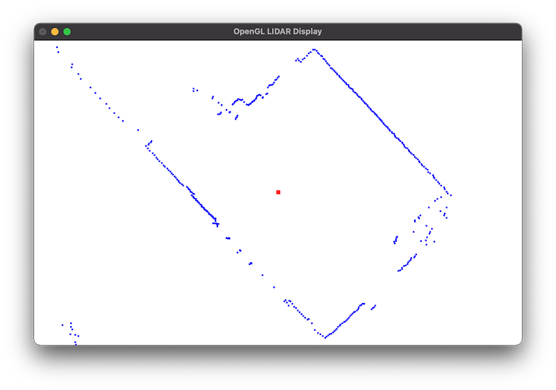
I recently purchased some dev kits, including a LIDAR kit. This past weekend I decided to learn how to use it to image my room as a stepping stone to my larger robotics navigation project. The funny thing about learning is that it often takes you on roads you didn’t expect to go. LIDARs are basically spinning measuring devices that use a laser to measure distance and send back angle and distance data. I wanted to visualize what the LIDAR was reading but the kit didn’t provide any imaging tools. So, I decided to learn OpenGL to render the output on my Mac. That became an exercise in itself but by the end of the weekend, I had a working project (see https://github.com/jasonacox/OpenGL-LIDAR-Display). It was challenging and frustrating at times. But as with any good learning effort, I had a Eureka moment that unlocked excitement and plans for future learning. I’m looking forward to the next phase!
What are you learning? When was the last time you had a Eureka moment? If you haven’t already, make plans this week to tackle something new to learn. Keep learning!