“In order to survive and win in the ever-changing world, keep updating yourself.” – Gordon Moore
Gordon was born during the Great Depression. His dad was the local sheriff. They lived in the small farming and ranching town of Pescadero, California. He was a quiet kid, but he was optimistic and hopeful. He loved the great outdoors and would often go fishing or play at the Pescadero Creekside Barn. He also love science. His parents bought him a chemistry set on Christmas one year which eventually inspired him to pursue a degree in Chemistry. He earned a Bachelor of Science at UC Berkeley and went on to receive his PhD at Caltech.
After college, Gordon joined fellow Caltech alumni and co-inventor of the transistor, William Shockley, at Shockley Semiconductor Laboratory. Unfortunately, things didn’t go well there. Shockley was controlling and erratic as a manager. Gordon and most of the other top scientists left after a year and joined Sherman Fairchild to start a new company. At Fairchild Semiconductor, Gordon and his friend, Robert Noyce, help devise a commercially viable process to miniaturize and combine transistors to form whole circuits on a sliver of silicon. This led to the creation of the first monolithic integrated circuit, the IC.
Gordon and Robert eventually left Fairchild and decided to form their own company. They would focus on integrated circuit development so they named their company, Integrated Electronics. They started making memory chips and focused the company on high speed innovation. The company did extremely well at first but also faced some difficult times that required significant changes. All the while, Gordon focused on pushing things forward and taking risks. They had to constantly reinvent themselves to survive. The company was later renamed to something that you might be familiar with, Intel.
Gordon believed that the key to their success was staying on the cutting edge. That led to the creation of the Intel 4004, the first general purpose programmable processor on the market. Gordon had observed that the number of transistors embedded on the chip seemed to double every year. He projected that trend line out into the future and made a prediction that the number of transistors would double at regular intervals for the foreseeable future. This exponential explosion that Gordon predicted would power the impact, scale and possibilities of computing for the world for years to come. Of course, you know that famous prediction. It was later named after him, “Moore’s Law”.
In 1971, the first Intel 4004 processor held 2,300 transistors. As of this year, the Intel Sapphire Rapids Xeon processor contains over 44 billion. The explosion of capability powered by science continues to accelerate the technology that enhances and amplifies our daily lives. This past Friday, Gordon Moore passed away at his home in Hawaii, but the inspiration, prediction and boundless technical optimism that he started continues to live on.
I know there is a lot going on right now. We are facing uncertainty and considerable change. It can create fear and apprehension. Technology is constantly being disrupted as well as its role, and our roles, in applying it to our businesses. While not comfortable, we need to embrace the change. Lean in and learn. We need to constantly find new ways to reinvent ourselves and what we do. Embrace the exponential possibility of the future! We can do this!
Moore’s Law – By Max Roser, Hannah Ritchie – https://ourworldindata.org/uploads/2020/11/Transistor-Count-over-time.png, CC BY 4.0, https://commons.wikimedia.org/w/index.php?curid=98219918
“The sculpture is already complete within the marble block before I start my work. It is already there, I just have to chisel away the superfluous material.” – Michelangelo
A tanker truck hauling 8,600 gallons of gasoline approached the MacArthur Maze, a large freeway interchange near the east end of the San Francisco, Oakland Bay Bridge in California. The driver, traveling faster than he should, lost control, hit the guardrail and overturned the load of highly flammable fuel. It spilled out on the interchange and exploded into a violent inferno, sending flames hundreds of feet into the air. The heat weakened the steel structure of the three-lane section of Interstate 580, causing the road to collapse onto Interstate 880 below. Thankfully, the driver survived and no other vehicles were involved in the accident.
California Department of Transportation, Caltrans, rushed in to quickly assessed the damage of this crucial interchange which handles some 160,000 vehicles per day. It would take weeks to clear the debris and several months to repair. Initial cost projections reached $10 million with an impact cost of $90 million. Bidding for the job started immediately. Due to the urgency of restoring this vital link, the state offered an incentive of $200,000 per day bonus if the work was completed before the deadline.
Bidding started. C. C. Myers had been planning for this his whole life. While other contractors in the room were offering on-time proposals well over the $10 million estimate, C. C. Myers shocked the room. He would do the work for $878,075, promising to complete the work well ahead of schedule. This was not the first time C. C. Myers had taken on heroic work. His company had a proven track record of rebuilding damage freeways well ahead of schedule, including the Santa Monica Freeway after the 1994 Northridge earthquake. Needless to say, he won the bid.
C. C. Myers went to work. He had assembled a logistic transport team and forged agreements in Texas and other areas to expedite steel delivery to the interchange. He streamlined processes and cut away any distractions and superfluous procedures that didn’t directly contribute to safely delivering the roadway ahead of schedule. As an example, the typical inspection process requires steel workers to complete all their welds before scheduling government X-ray inspection. C. C. Myers convinced the government to embed X-ray technicians in his team and perform the test immediately after the weld was complete. This allowed the crew to get real-time feedback on any area that didn’t pass and fix it immediately before moving on.
C. C. Myers’s efforts were successful. The monumental work was completed over a month ahead of schedule, right before a busy Memorial Day weekend. C. C. Myers earned a $5 million bonus for completing the work early. He quickly gave credit to his workers and their ability to deliver, but moving the mountain had required his artistry as well.
Like Michelangelo, C. C. Myers’s genius was his ability to stare into the mountain of “marble” and see what could be removed to reveal the ultimate outcome. Procedures and processes that didn’t directly deliver value were debris that had to be swept away. Every ounce of energy, every minute, and every movement was precious and deliberate. Everything that wasn’t part of the goal was chiseled away.
What is the work and marble before you right now? What is the goal? What sculpture are you trying to reveal? What can you remove? As all you wonderful artists head into your work channel your inner Michelangelo. Chisel away the useless motion, process and procedures to reveal the incredible work of art buried in the marble.
Credit: A friend of mine, Paul Gaffney, spoke on this at the 2023 DevOps Enterprise Forum. His story was far more eloquent than my version. It motivated me to do more research on the incident. The result is this post. I’m indebted to Paul for his inspiration.
Oh, no! We were several hours into a major system outage and there was still no clue as to what was broken. The webservers were running at full load and the applications were pumping a constant stream of error logs to disk. Systems and application engineers were frantically looking through the dizzying logs for clues as to the cause. Of course, looking at the logs, you would assume everything was broken, and it was. But even when the application worked, the logs were full of indecipherable errors. Everyone knew that most of the “errors” in the logs weren’t really errors, but untidy notices that developers had created long ago as part of a debugging exercise. As one engineer observed in some degree of frustration, “It’s like the log file that cried wolf!” After a while, nobody notices the errors.
The teams restarted services, rebooted systems, stopped and restarted load balancers. Nothing helped. Network engineers dug into the configuration of the routers and switches to make sure nothing was amiss. Except for the occasional keyboard typing sounds, dogs barking or children crying in the background, the intense investigation had produced an uncanny silence on the call. Operation center specialists were quickly crafting their communication updates and were discussing with the incident commander on how to update their many clients that were impacted by this outage. Company leaders and members of the board of directors were calling in to get updates. Stress was high. Would we ever find the cause or should we just shut down the company now and start over? Fatigue was setting in. Tempers were starting to show. Discussion ensued on the conference call to explore all mitigation options and next steps.
“I found it!” The discussion on the call stopped. Everyone perked up, anxious to hear the discovery. “What did you find?” the commander asked in a hopeful way. The giddy engineer took center stage on the call, eager to tell the news. “It’s the inventory service! The server at the fulfillment center seems to be intermittently timing out. Transactions are getting stuck in the queue.” The engineer paused, clearly typing away at some commands on his computer. “I think we have a routing problem. I try to trace it but it seems to bounce around and disappear. Sometimes it works, but to complete the transaction, multiple calls are required and too many of them are failing. I’m chatting with the fulfillment center and they report the inventory system is running.”
The engineer sent the traceroute to the network engineer who started investigating and then asked, “Can you send me the list of all the addresses used by the inventory system?” After some back and forth, the conclusion came, “I found the problem! There are two paths to the fulfillment center, one of which goes through another datacenter. That datacenter link looks up but it is clearly not passing traffic.” After more typing, the conclusion, “Ah, it seems the telco made a routing change. I’m getting them to reverse it now.” Soon the change was reversed and transactions were flowing again. The dashboards cleared and “green” lights came back on. Everyone on the bridge quietly, and sometimes not so silently, celebrated and felt an incredible emotional relief. Sure, there would be more questions, incident review and learning, but solving the problem was exhilarating.
How many of you can relate to a story like that? How many of you have been on that call?
A friend of mine, Dr. Steven Spear at MIT, often reminds us that the key to solving a problem is seeing the problem. You can’t solve what you cannot see. A big part of reliability engineering and systems dynamics is understanding how we gain visibility into problems and surface them so they can be addressed. Ideally, we find those weaknesses before they cause real business impact. That is often the attraction of chaos engineering, poking at fault domains to expose fractures that could become outages. But sometimes the issue is so complex that we just need a clear line of sight into the problem. In the story above, connectivity and those dependent links were not clearly visible. If there was some way to measure the foundational connectivity between the dependent locations, our operational heroes could have quickly seen it, fixed it, and gone back to sleep. Getting that visibility in advanced is the right thing to do for our business, our customers and our teams.
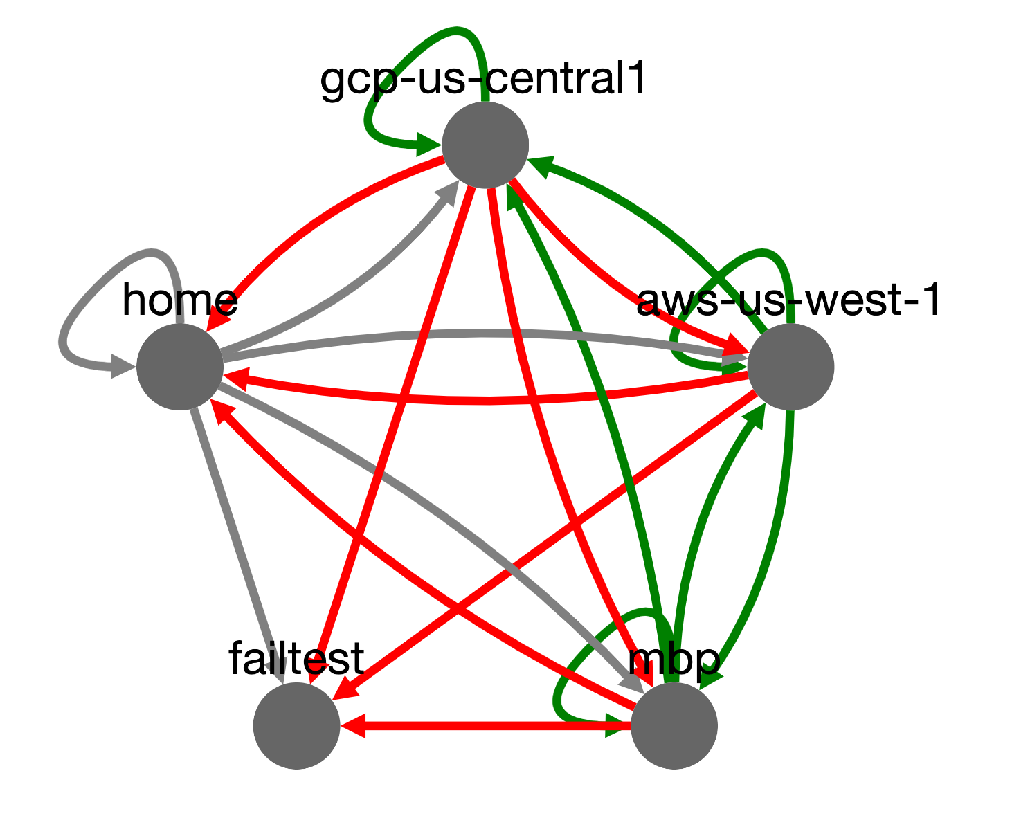
This past weekend, I found myself itching to code and tinker around with some new tech. The story above is one I have seen repeated multiple times. We often have limited visibility into point-to-point connectivity across our networks and vendors. Yet we have this grid of dependency that is needed to deliver our business powering technology. I know what you are thinking. There are millions of tools that do that. I found some and they were very elaborate and complicated, way more than what I wanted to experiment with. I finally had my excuse to code. I wanted to build a system to synthetically monitor all these links. Think of an instance in one datacenter or cloud polling an instance in another datacenter or region. I had a few hours this weekend so I blasted out some code. I created a tiny multithreaded python webservice that polls a list of other nodes and builds a graph database it displays using the JavaScript visualization library, cytoscape ,which was fun learning by itself. Of course, I packed this all into a container and gave it the catchy name, “GridBug”. Yes, I know, I’m a nerd.
You can throw a GridBug onto any instance, into any datacenter, and it will go to work monitoring connectivity. I didn’t have time to test any serverless options but it should work as well. I set up 5 nodes in 3 locations for a test, with some forced failures to see how it would detect conditions on the grid. The graph data converges overtime so that every node can render the same graph. If you want to see it, here is my test and project code: https://github.com/jasonacox/gridbug
I have no expectations on this project. It is clearly just a work of fun I wanted to share with all of you, but it occurs to me that there is still a lesson here. Pain or necessity is a mighty force in terms of inspiration. What bugs you? Like this outage example, is there some pain point that you would love to see addressed? What’s keeping you from trying to fix it? Come up with a project and go to work on it. You are going to learn something! Look, let’s be real, my project here is elementary and buggy at best (sorry, couldn’t resist the pun), but I got a chance to learn something new and see a fun result. That’s what makes projects like this so rewarding. The journey is the point, and frankly, you might even end up with something that brings some value to the rest of our human family. Go create something new this week!
We had assembled to put together the outline for a guidance paper. At the top was the title, “Modern Governance.” I thought to myself that the title alone would cure insomnia. Despite the title, members of the team had developed brilliant new automation and approaches. They were already deploying those game changing ideas at their businesses. We wanted to share those! Unfortunately, the gold was buried in the boredom. It was too academic and dry. Nobody would make it past the title, much less the layers of governance tedium in the outline. Energy in the room which had been off the chart during the discovery discussions suddenly fell flat as we all realized that our guidance document would have little impact on the real world.
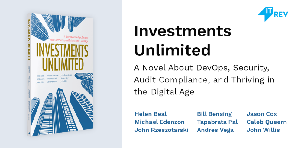
“Hey, I have an idea! Why don’t we just tell a story?” I suggested, “Imagine a Phoenix Project moment where a crisis hits and a band of characters have to solve it.” Enthusiasm erupted as the group piled on with ideas on how the story could unfold to show and teach the thoughts we had captured in the dry outline. Suddenly, characters emerged. Susan, the CEO was getting an urgent phone call about an existential crisis hitting her company. Bill, Jada, Michelle, Jason and the rest of the cast of character sprung to life in a brief narrative. We put the story to paper and changed the name to Investments Unlimited, inspired by the fictitious company in the Phoenix Project. We had done it! A short story was assembled and we presented it to the rest of the DevOps Forum who applauded the work. Mission accomplished. Or so it seemed…
A few months later we were invited to a meeting. “Gene Kim and the staff at IT Revolution reviewed your paper and we have a proposal.” Leah, the editor for IT Rev and the Forum papers explained to us, “We think the paper is great, but we think it could be greater. We would like to turn it into a novel.” She paused and surveyed the group. John Willis, the leader of the forum group and fellow co-author, suggested, “I think we should do this! It would take some work, but we should write it ourselves and add some of the details that we couldn’t develop before. What do you think, are you up for it?” We were all stunned and delighted. One by one, we all chimed in that we would love to take on the challenge. Shortly after that call we started meeting every Tuesday evening to work on the book. We invited industry experts to interview and fill in the gaps of our understanding. Weekends became a writing club where some of us would meet to knock out a scene, develop a character or wordsmith a moment. Slowly the short paper became chapters, and the chapters became a novel.
I confess, I was enamored just to be part of this great group of co-authors. This cast was made up of an incredible family of industry thought leaders, technical gurus and fellow DevOps rebels: Helen Beal, Bill Bensing, Michael Edenzon, Tapabrata “Topo” Pal, Caleb Queern, John Rzeszotarski, Andres Vega and of course, John Willis. Our meetings would sometimes pivot into philosophical discussions, technology news or current DevSecOps challenges. Despite the frequent distractions and detours, we managed to nudge the narrative forward, week by week.
Writing a book is hard. You are turning ambiguous ideas into letters on a page. The key was to just keep writing, keep the prose flowing. There were times where you wouldn’t feel inspired or enthusiastic about the words pouring out of your fingers, but you would keep typing. I was surprised and amazed at how well that worked. More than once, I discovered that inspiration followed effort. The act of doing created a warming glow. Suddenly the arduous task unlocked a love, a passion and an inspiration that wasn’t there before. That approach developed new twists in the story, new ideas to explore or challenges to solve. But getting those words on the paper were important. We would spend months editing and tweaking the story, but without that original content there would be nothing to work with. Eventually we would have a finished product and as of two weeks ago, a published book. It was an experience that I will forever cherish and recommend to anyone who gets the opportunity to do the same.
Just keep writing. Going through this journey has reminded me of the importance of “doing,” self-motivation and determination. I think we can all get stuck in limbo, waiting around for that magical moment of inspiration. The truth is that in life, that inspiration is often the result of the wind of our own movements. Just keep going! Inspiration will come. Words will become chapters and chapters will become stories. What are you penning today? What adventures are you crafting by your doing? Get up, get moving… keep writing.
Investments Unlimited A Novel About DevOps, Security, Audit Compliance, and Thriving in the Digital Age by Helen Beal, Bill Bensing, Jason Cox, Michael Edenzon, Dr. Tapabrata “Topo” Pal, Caleb Queern, John Rzeszotarski, Andres Vega, and John Willis
“On the other side of the screen, it all looks so easy.” – Kevin Flynn
Greetings programs,
“LaserDisc… Prepare to be blown away!” The clerk at the local movie rental store handed us the LaserDisc player and movie and guaranteed that it would level up our home movie experience. My brother and I unpacked the dazzling new player and quickly connected the RCA cables, powered up the audio system and hit play. Seconds later it sprung to life with colorful geometric shapes flying across the screen, taking us on a journey into a virtual realm. The dazzling images on the screen were accompanied by room filling sounds the LaserDisc pumped into the audio system. The ethereal soundtrack by Wendy Carlos transported us into this magical world of the impossible. The characters in the movie were playing video games, but not like my sister and I would play at the local arcade, they were actually in the game, inside the computer! They were “programs”, walking around, pulling power from circuit board rivers of light, recording information on their identity disks, piloting vector based light-cycles, tanks, recognizers and solar sailing ships across the grid. And like any good hero story, they fought against the oppressive evil overlord. The Master Control Program sought to enslave the world of computer programs to do it’s evil bidding to ultimately take over the human world. They were fighting for the “Users”, the human creators of this digital realm. One of those creators, a programmer named Flynn, gets transported into this digital world to join in on the fight. Welcome to the world of TRON!
I was blown away! The clerk had been right. It had inspired me and introduced me into a new world. The world of programs, computers and computer graphics. I was suddenly obsessed with this new found passion. It became an imperative for me to learn everything I could about this computer world. I managed to talk my dad into getting me a Commodore 64 so I could learn to do all these things that I had seen on the screen. Soon, I was crafting my own programs, sprites, animations and audio waveforms. I even made my own space adventure game that I published in our middle school paper, as if anyone would ever type in all that code! I was hooked. Maker clubs, hacker homebrew meetups and bulletin board systems eventually led me to join the computer science and electrical engineering departments at the University of Tulsa. I knew what I wanted to do. I wanted to fight for the Users, making programs and systems that made the world a better place.
TRON was released to theaters 40 years ago this past weekend. While not a blockbuster for Disney by any means, the film was groundbreaking. As with so many of Disney films, it had inspired people just like me. It even paved the way for computer-generated imagery in animated films. John Lasseter has said that without TRON, there would have been no Toy Story.
We make magic. But that magic isn’t just the compelling storytelling, the visual effects, the powerful adventures or experiences we deliver. No, the real magic is what endures those moments and begins a ripple effect on lives. People become inspired to try new things. New passions awaken. New worlds unfold. The work we do makes an impact that transcends the bottom line and propels us into the future as a species. We inform. We inspire. We improve our human experience, one story at a time.
Are you ready? It’s time to go play the game. Let’s go fight for the Users!
After research and talking with several solar companies, we decided on an 8.5kW Tesla Solar plus Powerwall+ system with their new high efficiency 425W panels. The main reason for our decision was the low cost, handsomely framed panels and the whole house backup capability. Other solar companies had good backups systems but we did not find any who would provide whole house backup. And, more importantly, we were delightfully surprised to see that Tesla came in with the best price. Having said that, we would soon discover that they seemed to have significantly reduced overhead by mostly eliminating customer service.
The Install
25 September 2021
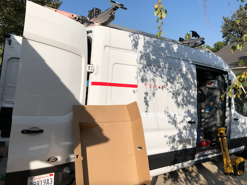
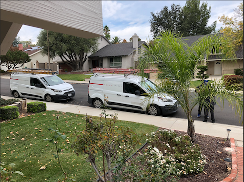
Tesla Crew
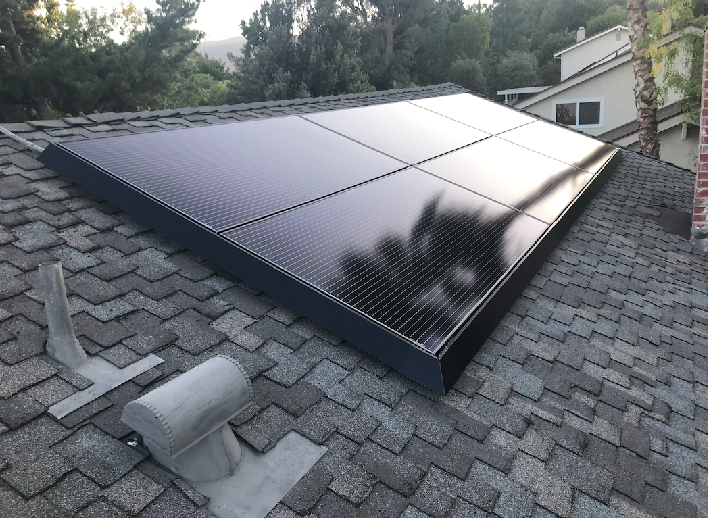
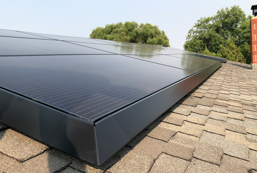
After ordering, reviewing designs, applying for HOA and City approval, we were finally ready to get the system installed. Two different crews arrived over a span of a week to get the system installed. The panels went on first. The panel install crew was professional and friendly. However, when they left I noticed that the handsome skirts (frames) we were so excited about were only installed on the front of the house (street facing roof). It looked great but I had expected to get them on the back as well. I reported it and in just a few days a technician came out and added the skirts to the back roof panels. He explained that they usually only install the skirts on the front. So, please note, if you want skirts on all your panels, make sure you let them know in advance. Also, the skirts are only put on the left, right and bottom. There are no skirts on the top to allow heat to escape from the panels during the hot summer.
Panel Mount – Torx T30
While installing the skirts for the back, I noticed one of the panel edges was sticking up about 1/2″ higher than the rest. The technician tried to fix it but he didn’t have all the tools. He only had what was needed to install the skirts. He asked me if I had a Torx T30 driver. I didn’t but he explained how I could adjust the panels myself. I picked up a T30 at our Newhall True Value store. I climbed up on the roof and found the adjustment area. I used a vice grip on the screwdriver to get enough leverage (mostly because I’m pretty weak especially when I’m up on the roof). I was able to lower the panel 1/2″ so it was flush. It looked beautiful.
FrontBack
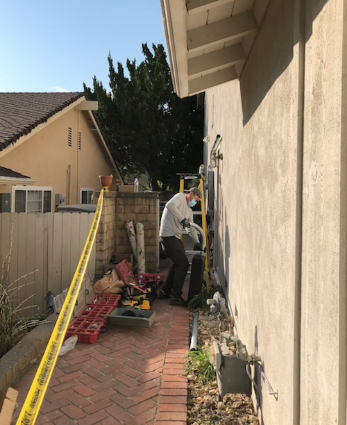
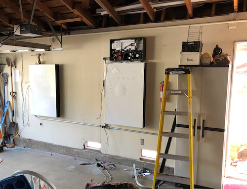
A week later, another crew showed up to wire it in and commission the system. This meant a day without power, but we were prepared for that. I tried not to be a nuisance, but couldn’t help but watch and ask questions. I made sure all of the crew had plenty of bottled water, Gatorade and snacks, including ice cream candy bars since it was so hot. They installed the Powerwalls in our garage and wired in the breaker panels and Tesla Gateway by the utility meter. After everything was installed, they powered it up and began the commissioning process.
The Problem
During commissioning, the first signs of trouble started showing up. The installers downloaded the latest software updates but were unable to get the Solar Panels to work correctly. The solar assembly was only producing 160W in full sun which doesn’t even show up in the app. They tried for hours, upgrading, rebooting, calling. They eventually gave up after showing me that the Powerwall could power our house if they cut the mains (based on 22% charge from the factory). They explained that Tesla would send out a software patch to fix the Solar panels, most likely.
I contacted our Tesla Advisor to report the problem and to see if they had an update. After several days of emailing, texting and calling, I received a note from the advisor that our inspection would be scheduled in 3-4 weeks and he would contact the electrician about the problem. I spent another week requesting updates but my Advisor had gone radio silent. It turns out that this is a common experience with Tesla. Assuming best intentions, I can only imagine that the advisors are understaffed and overwhelmed. Regardless, it all results in a very frustrating experience for the customer.
I did manage to finally get an update and a promise to further investigate the issue. While I waited, I decided to do some more research on the system to see if I could find the problem myself…
HIGH VOLTAGE WARNING: I need to stop here and remind everyone that these systems contain extremely high voltages and are dangerous. Hopefully it goes without saying, but please be careful if you poke around inside these electrical boxes. High voltage can be fatal.
The Investigation
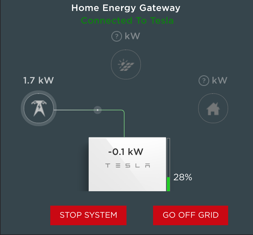
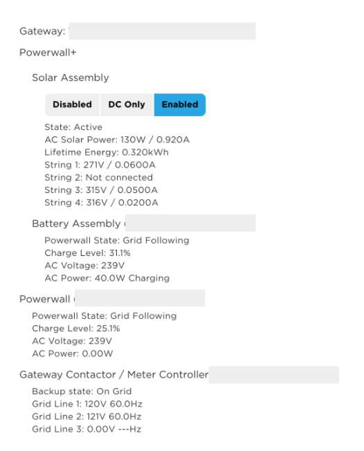
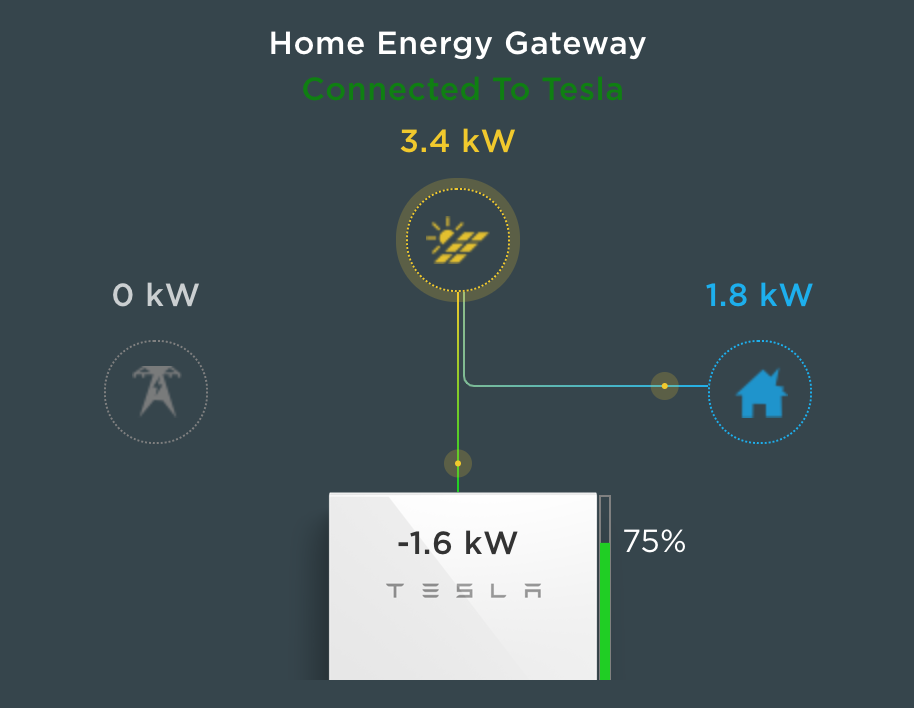
You can connect to the Tesla Gateway by scanning the QR code inside the box. It will have your phone connect to the Gateway’s access point. You will need to stay close to the gateway if you connect this way (and browse to https://192.168.91.1). However, keep in mind that it is also connected to your home network and if you know how to find the IP address, you can point your browser to that IP and login as the Installer to see more details about the system. Your browser will likely require that you ignore the security certificate warning (more on this in the observations section below) and you will need to toggle the power switch to one of your Powerwalls but it will let you in. That is essentially their 2nd factor system to ensure you are authorized. Here is what my system looked like after installation on the main screen and on the “System” screen :
The System screen also shows details about the solar generation, Powerwalls and power usage:
Below the above list was a section for “Remote Meter” that would occasionally appear. This was particularly interesting:
Remote Meter (Vxxxxxxxxxxxxxxx) CT 1 (Solar): —W
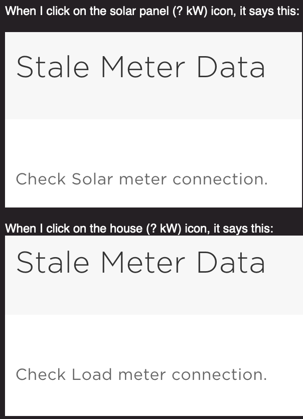
That seemed odd. Also when I clicked on the solar panel icon on the main screen, it would say “Stale Meter Data” – that had me wondering if the solar meter was the real issue.
The Fix?
I first disabled the Solar Assembly by clicking “Disable” on the System screen.
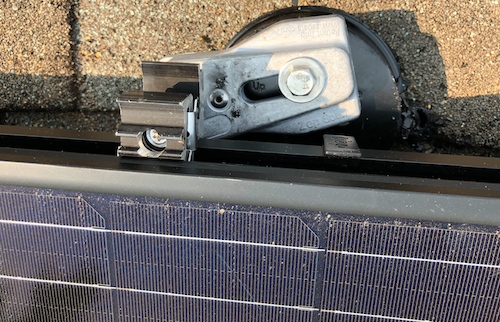
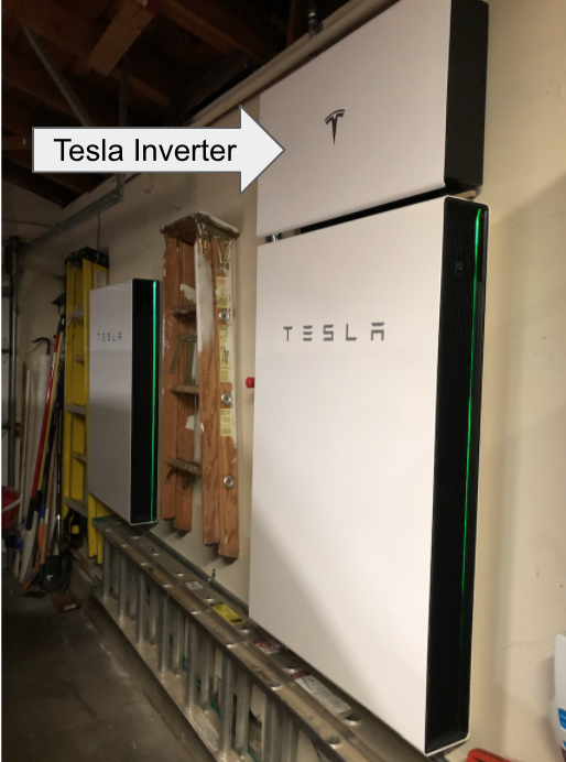
I opened up the Inverter, the box above the first Powerall. There is a small latch on the bottom that will unlock and let the panel swing up. I found a wooden dowel to prop it open so it would bang on my head the whole time I was investigating.
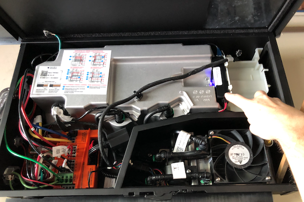
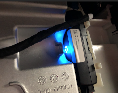
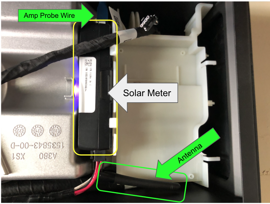
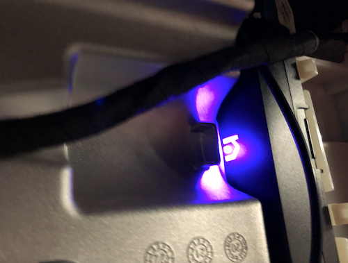
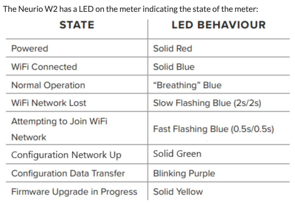
I noticed that there was a box on the right that had a “n” LED flashing. The code on the box was the same code that was listed as the “Remote meter” in the system’s display (the one showing no power). Some more research and I discovered that this module is a Neurio W2-Tesla WiFi based current reader that sends the solar power data to the Gateway.
Neurio was recently purchased by Generac but you can still find manuals and some models for sale online. This particular model, W2, has been customized for Tesla. It is designed to connect to the access point of the Tesla Gateway and send the solar power data.
CT-1 Amp Probe Wire
The Neurio has a wire plugged in to the top in the CT-1 (current transformer) port. I traced it over to the solar inverter where a clamp is wrapped around the solar inverter output AC line to measure the amperage. I re-seated that connector.
Antenna
I then noticed that there was an antenna jammed below it that was tucked to the left, under the massive metal inverter shield. I turned the antenna to the right, in the open unshield space.
As soon as I did these two things, the LED “n” on the box began to change and a tune started coming out of the box. It sounded like “I am connected now”. The flashing “n” became a solid blue light.
Eureka!
I went back to the System screen and re-activated the Solar Assembly by clicking “Enabled”. This takes several minutes and you will see the system go through and activate the solar arrays, test relays and impedance before the assembly comes online.
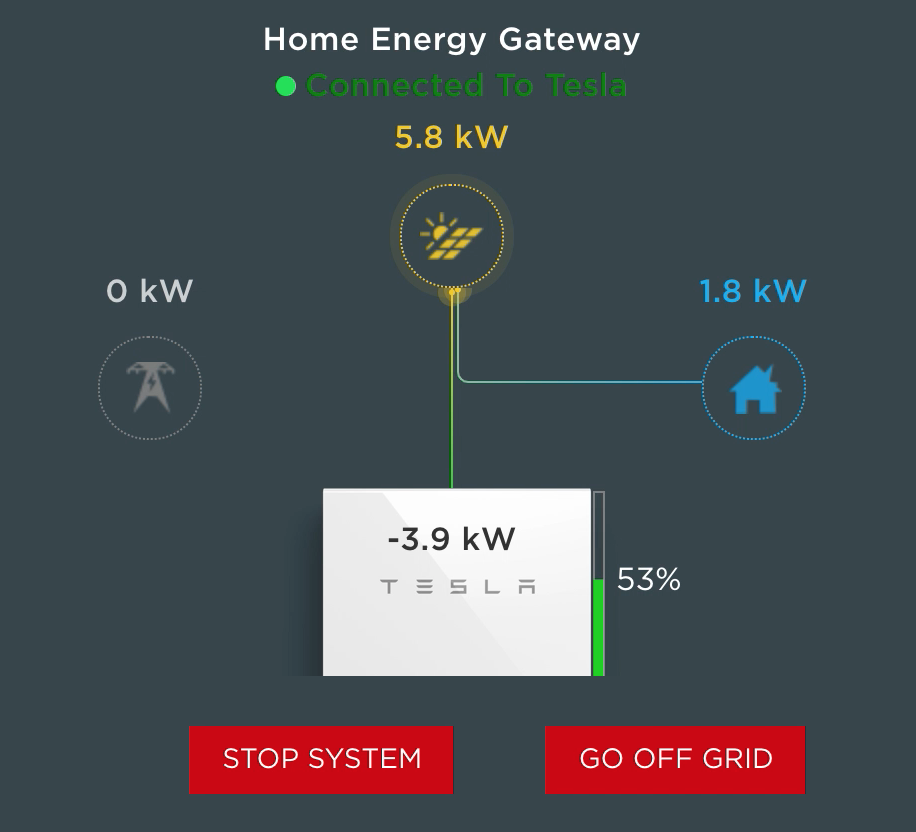
As soon as the Solar Assembly came online, I started seeing kW of power show up on the Systems screen. 5800W of power was coming in, fully powering the house and charging the Powerwalls!
Not so fast…
Sadly, just two hours later my elation was destroyed. The solar energy dropped back to zero.
I checked the inverter. Sure enough, the Neurio was flashing again. I attempt the above process again, several times, but no joy this time. It would chime and go green, but then started flashing again. Based on my research, the Neurio connects to the Tesla Gateway WiFi only. The beeps and flashes indicate that it is unable to connect to the Gateway WiFi.
One thought I had was to reach out to Neurio (which is now owned by Generac) to see if they could provide the API, pinout or schematics for the W2 device so I could troubleshoot at the firmware and component level. When I contacted them, Generac replied that the serial number for my device contains proprietary firmware by Tesla that they cannot support. They recommend that I contact Tesla at: 888-518-3752. Oh well, it was worth a shot.
The Workaround
I love a challenge. In fact, when something isn’t working, it is almost an addiction to me. I have to figure it out and fix it! So, I had two thoughts at this point. First, I wanted to see what the Neurio was actually doing. I thought about setting up an ESP8266 to be an WiFi access point to intercept the Neurio’s communication attempts with the Gateway. But before I do that, it occured to me, I wonder what would happen if the system didn’t have a solar meter at all. In my investigation, I discovered that the solar power meter feature is often an add-on or post-install enhancement. Maybe this was more of an add-on feature than a requirement?
At the minimum, I wanted to see if there are alternatives to the Neurio in the Tesla configuration. Unfortunately, there isn’t an easy way to edit this data. I discovered that settings could only be set during the initial setup time. That would require running the setup wizard again. I decided to be bold and fire up the installation Wizard. At the bottom of the system portal is the “Run Wizard” link. Of course, I clicked it.
WARNING: I’m fairly confident that you can completely break your Tesla Solar setup using the Wizard, maybe even disable power to your house permanently. It is intended for installers. I’m taking the risk, but you should consider this first and be cautious about proceeding. I’m also fairly confident I’m going to void something in the process, but if you put something in my house, fair game, I must hack.
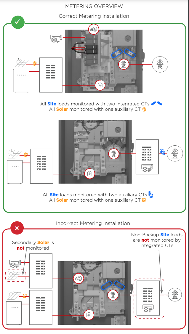
The wizard is straightforward. It requires you to Stop the system, but the settings are mostly intuitive. When I arrived at the Meter screen, it had 3 different meters displayed. I apologize, I did not take screenshots but will update this blog if I capture them in the future but the screens are very basic.
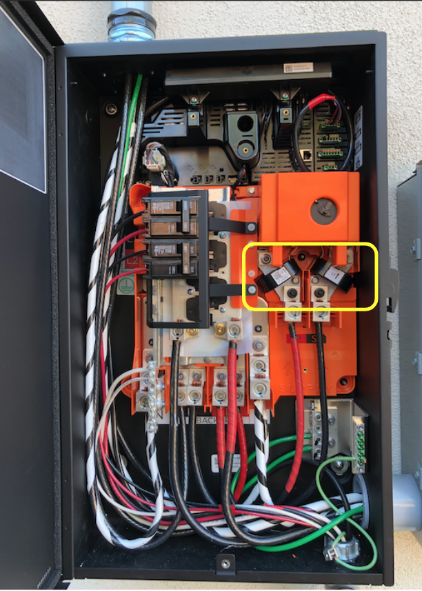
Two of the sensors were for the built-in CT’s used to measure the power in the Tesla Backup Gateway (you can see them on the main bus if you open the Gateway panel – which I did).
Tesla Backup Gateway DANGER: High voltage – Seriously!
These tested extremely fast (subsecond) were working correctly and tested “good”. The third meter, a WiFi meter, was the Solar Meter (Neurio) and it’s status was Error, unable to connect. I clicked the connect button which reported it would take 3 minutes to configure the WiFi sensor. No shock, it didn’t work. I tried it 3 more times. The “Advanced” drop down allows you to add MAC address and IP, but this didn’t help. There was a “Delete” button. I thought it might be worth a try to delete and re-add. At the bottom were options to add “WiFi” or “Wired” CTs. I tried to add the Neurio (WiFi) again, multiple times, rebooting the Neurio occasionally to see if that would help. Nothing.
Here is where something interesting happened. The Wizard would NOT let me advance because the WiFi sensor was not healthy (connected). Hum… Well, I figured I would just have to delete it to see what other screens I could find in the Wizard. I deleted the Neurio. I advanced to the next screen and was presented with a “Warning – you do not have a solar sensor selected.” Naturally, I ignored that and continued.
Commissioned! I completed the Wizard setup and the system came back online. Surprisingly, the system screen looked basically the same but the dynamic flow diagram was actually working. There were no sensor errors or warnings. Power was flowing from the Grid to the House. It was the middle of the night so I signed off and went to bed.
I know what you are thinking. This is dangerous, right? I mean, we seemed to have removed solar power observability from the platform. Will the Gateway and Inverter sill know what to do? Well, it turns out… it does!
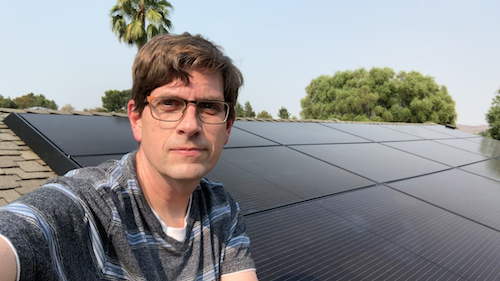
The Power of the Sun
Next morning, I woke to discover solar generation was charging the powerwalls and our house was completely powered by the sun! I still want Telsa to fix the Neurio or, better yet, provide some hardwire CT to monitor Solar power generation. I’m assuming that the display below means that the Gateway is computing the the solar generation based on other CTs. In any case, my workaround is in place and we now have a working system again.
As I’m looking at my phone, I realize… I’m holding the power of the sun in the palm of my hand. Yes, that is a geeky Doc Ock reference. We are now powering our home with an ancient but reliable and self-regulating, thermonuclear fusion reactor… our sun.
The Return of Tesla
1 November 2021
I gave up on waiting on Tesla to respond to me about the Neurio. I figured it didn’t matter since I had a working system. A month after the install and I still didn’t have an inspection date. Then it happened. I received a text message and email from Tesla that my inspection was scheduled. There was NO DATE or TIME given. Instead of asking, I figured it didn’t matter. We would see what would happen.
The day of inspection had arrived. A surprise knock on the door and there was Ishmael from Tesla. He explained he was there to meet with the City inspector for the final inspection. I showed him the gear, the Powerwalls, the gateway and the breaker panels. He looked at me and asked, “Did the install crew not put on the warning labels?” Nope.
This was something I had noticed after the installers left. In the Tesla plans are specific instructions on where to place the red warning labels on all of the gear. It includes a helpful diagram for anyone wanting to know how to kill all power in case of emergency. I had raised this issue with my project advisor a few times, but as usual, told me he would look into it and of course, nothing happened. I explained this to Ishmael who rolled his eyes and expressed apologies and said he would need to call to get the labels or it would not pass inspection. He would wait for the delivery and get them installed and ready for the City.
Shortly after meeting Ishmael, another Tesla vehicle pulled up. I figured it was the inspection stickers, but instead, it was Rocío, a Quality Assurance technician. She told me that her job was to make sure everything was installed correctly and running. I almost hugged her! I expressed my delight and appreciation that she would check on us. I explained everything that happened including how the installers said it must have been a Tesla software bug and gave up after trying for hours to get it work. I also told her about the Neurio hack I had done to get it working. She was shocked, sympathetic and determined to fix the issue.
Naturally, Rocío attempted to reset the Neurio and discovered the same thing that I did, with the exception that she was able to get the Neurio to work if she held the connector, pressing on it in a certain way. “There is clearly something wrong with the hardware and it needs to be replaced,” she concluded. I hate to be cynical, but I was definitely thinking this new chapter in my Tesla adventure would turn into an multi-week RMA, repair order and a return visit that may get scheduled sometime next year, if I’m lucky.
To my delight, Rocío looked straight at me and said, “And we’re going to get this fixed today!” She was right! She made a phone call and 30 minutes later another Tesla van showed up with the replacement Neurio!
Rocío got it working. Less than 30 minutes later she had the entire system back online and working correctly. “That’s amazing!” I told her. She clearly saw my astonishment and said, “I used to be an installer, I know what’s needed.” Well, that was completely accurate. She didn’t stop there. She examined all the gear and climbed up on the roof to ensure all the panels were in good order.
Shortly after the good news, the warning labels arrived and were attached to the new gear, ready for the official inspection. I started passing out my sincere appreciation, candy bars, water and Gatorade to these brilliant Tesla soldiers that had come to save the day. After bidding farewell to our new friends, Rocío drove off on her shiney white stallion… uh, I mean Tesla van.
About 30 minutes later, the City Inspector arrived and after a quick survey of the installed gear with Ishmael, signed his approval. Now we are on to the Permission to Operate (PTO) by Southern California Edison.
Power Gremlins
3 November 2021
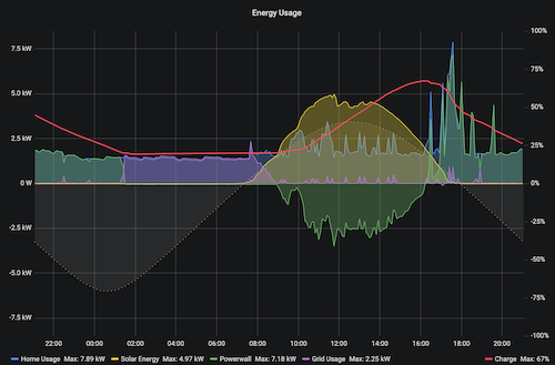
I should definitely learn to be more guarded in my optimism about this Tesla adventure. After two days of having the new Neurio re-installed, I started noticing something odd. After solar production when I would expect the Powerwalls to kick in and power the house, I would see grid power start to show up and the Powerwalls drop to zero. It would only last for a few minutes then return to normal operations. Looked at the Powerwall Dashboard I set up and can even see the grid power spiking during the day when solar production was more than enough to power the house.
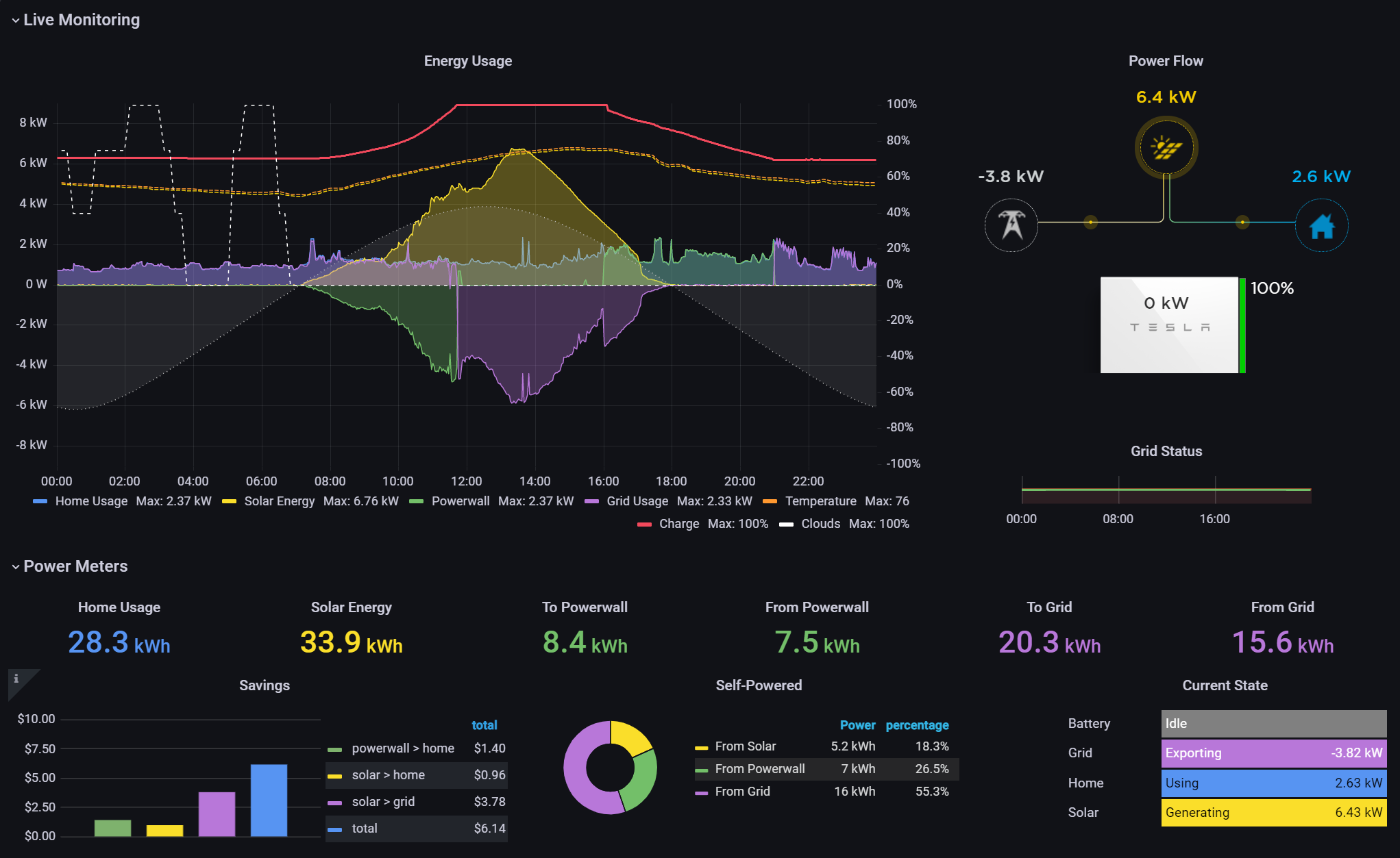
Powerwall Dashboard: Notice the purple (grid power) spikes throughout the day. These just started showing up after the new Neurio was installed.
The grid power spikes did not exist before the new Neurio. I went out to look at the inverter. The Neurio’s purple light was mostly solid but would “flicker” blue. It was random, like a candle flame not like the error condition of the previous Neurio. It was happening constantly as I watched. When the flickering would get bad, I would see the powerwall drop to zero and grid power surge. There seemed to be a correlation. At any rate, I wasn’t going to let the flickering continue.
HIGH VOLTAGE WARNING: I need to stop here again and remind everyone that these systems contain extremely high voltages and are dangerous. Hopefully it goes without saying, but please be careful if you poke around inside these electrical boxes. High voltage can be fatal.
I powered off the Neurio by unplugging the power next to the antenna at the bottom. I noticed the antenna was once again tucked under the massive shield. I guess that was the typical install. I changed it so it was pointing away from the inverter shield and reworked the cables to plug it back in. The Neurio went through the startup (flashing, then solid green, then blue and then purple). I watched it for a while and noticed it stayed solid purple, no flickering.
I don’t know if this was a fix or a sign of things to come. Other people have reported similar problems with the Neurio, including a YouTube video on how to reset it the way I did. It is rather shocking how unreliable this little box is. I understand it is a “revenue grade” meter which is likely why Tesla is using it, allowing them to report “Solar Renewable Energy Credits” (SRECs). The Inverter itself seems to have a decent meter without the Neurio which is why my workaround hack worked while waiting for the Neurio replacement. If the reset doesn’t work, I will likely revisit my “fix.”
5 January 2022
The “fix” was temporary. It appears to be a resource leak that requires the Neurio to be restarted. The good news is that Tesla finally recognized the instability and sent out a 21.44 firmware update that fixed the Powerwall from disabling solar when the Neurio goes into a bad state. Finally! I was planning on ripping the Neurio out after PTO, but now I don’t have to do that. I’m currently on firmware 21.44.1 and just heard from the community that others are seeing an upgrade to 22.1 that also upgrades the Neurio from firmware “1.6.1-Tesla” to “1.7.1-Tesla” (you have to access the vitals API and decode the protobuf binary payload to see this – see here). Hopefully that helps with stability.
Permission to Operate
2 February 2022
PTO, finally! Our utility company, Southern California Edison (SCE) granted permission to operate. It took Tesla several tries to get the PTO request submitted correctly. SCE was notifying us of all the transactions but we were not able to see the full application or help. Believe me, I tried! In any case, our installation adventure has finally come to an end. It has been seven months since we started this epic journey. It is good to finally have a fully operational system.
To be fair, we have had a working solar system with Powerwall backup since October, but without PTO. PTO means that our system is no longer in self-consumption test mode. We can now push excess solar production to the grid for a credit. For the first time ever, we see grid graph going negative!
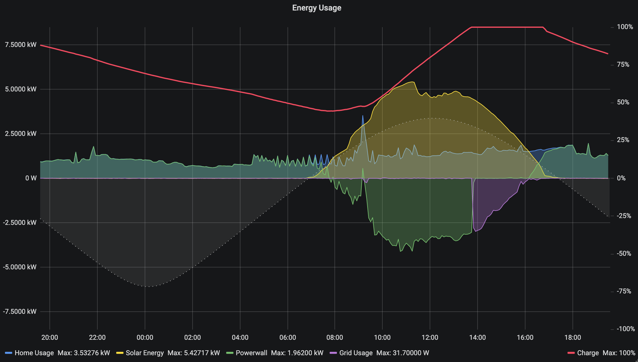
24 hour graph of energy usage including Powerwall (green) charging and pushing to the grid (purple).
Conclusion
The Tesla Solar system has been an adventure for us. I don’t regret going with Tesla even though they have improvement areas, especially related to consumer experience. We love the look of the panels and the equipment. In typical Tesla fashion, the design is stunning and feels like quality. If you do select Tesla Solar, my advice is to plan on being the project manager. Stay on top of the details to keep things moving and make sure items are not dropped.
Regardless of who you go with, I recommend you set some non-negotiables to help you filter. Here were my non-negotiables:
Aesthetics – We wanted something that looked high-tech, neat, clean and symmetrical on our roof. I wanted the dark panels (no white lines) with a clean looking frame.
Whole House Backup – We wanted batteries capable of running our house over 24 hours in the event of a power outage and a system that would charge the batteries during the day even if power was out for extended days.
Home Automation and Monitoring APIs – I wanted a system I could hack, use tools to monitor, dashboard, trend and even make decision on home automation components to optimize our energy usage.
Off the Grid – We wanted the system sized to allow us to be self sustaining with no need to use the grid even at night, fully expecting that at some point Net Energy Metering disappears or becomes less attractive, the system will still provide us with a zero grid usage option.
This helped considerably. It eliminated the list down to a handful and the lowest cost on our list was Tesla, who also had the best aesthetics IMHO. Now to be clear, as I mentioned above, Tesla is seeing explosive demand for their option and their customer service struggles a lot. I also had the opportunity to work with several incredible Tesla technicians who helped us.
I am extremely happy with our Tesla system and would recommend it to anyone, despite the bumps along the way. Tesla hit on all my non-negotiables and is elegant, fun and powerful. It has become a delightful hobby as well as a powerful utility for our green energy mission.
While a similar adventure may not be for everyone, if you are in the market for a Solar system, I still highly recommend checking out Tesla’s options. Use this link and you can save $300 if you do order and I get a reward too: http://ts.la/jason50054
I have to confess. I love toys. To me, this new Tesla Powerwall+ Energy systems is a gigantic (and expensive) toy. I have thoroughly enjoyed tinkering with the system and building electronic accessories and software to manage it. As you have seen in this post, I wrote my own python API library (pyPowerwall) and created a Powerwall Dashboard to better see what the system is doing over time (credit to other open source projects I mention below).
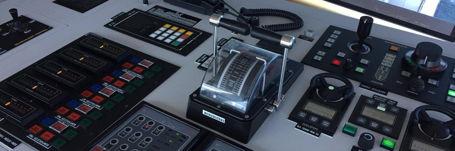
One thing that the Tesla is missing is a good instrument panel display. Sure, you can run the app all the time, but I wanted something that would show the solar production and other details like a physical dashboard but without opening an app. I built one. It is hanging next to the Powerwalls in our garage. Much to my wife’s initial trepidation, I also built one and hung it in our kitchen. It turns out that I’m not the only one to appreciate it… well, after a while anyway. 🙂
Here are some of my toys that I gladly share with you. Please reach out and let me know if you find these useful:
pyPowerwall Dashboard with String Data
PowerwallWeb Dashboard – The Tesla App and web based portal present great animations showing the solar generation and usage. However, the information is very limited and not design for visualizing the energy data in multiple ways. I wanted to see a year at a glance as well as the string data (how much power each group of solar panels on the roof are producing). I found this Grafana based dashboard and made some minor changes including the addition of my own python based Powerwall API Proxy. Here is a simple python API module pyPowerwall to pull data from the Powerwall Gateway using your “customer” credentials: https://github.com/jasonacox/pypowerwall. If you are wanting your own Powerwall Dashboard, it is fairly easy to set up with the instructions here using Docker Compose: https://github.com/jasonacox/Powerwall-Dashboard#powerwall-dashboard
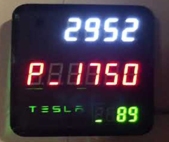
Powerwall Digital Display
Powerwall Wall Mounted Display – I really wanted to see the current solar generation and state of the Powerwall on a simple LED digital display. I 3D printed a Tesla themed case and installed the displays to show solar, house, battery, and grid power data. The display show the solar production power at the top. House, Powerwall and Grid power data rotate through the middle display and the battery level of the Powerwalls is at the bottom (89% in this picture). You can see a video of the display running below.
The display uses a WiFi enabled systems-on-chip (SoC) ESP8266 WeMos controller and three simple TM1637 7-segment LED display modules. Naturally I used my own Arduino API library (TM1637TinyDisplay) for those and the pyPowerwall proxy to display the results. It would have been nice if Tesla had built a wall monitor to show vitals like this. I’m sure it would have been a nice animated OLED display of some sorts. But this was fun. I needed to build another toy and I love my retro-LED display. If you want to build your own, I have open sourced the design and code and uploaded here for you to use: https://github.com/jasonacox/Powerwall-Display
I took note of several areas of concern and improvement during my investigation and problem solving. I have recorded them here.
WPA TKIP Command Access Point – The Tesla Gateway uses this weaker method to host its WiFi access point. As I discovered the Neurio uses this same access point to send Solar Power data (if it works). WPA TKIP has been dropped due for security reasons and more modern access points use WPA2 and AES encryption (WPA2-AES).
HTTPS Security Certificate – The HTTPS certificate the Gateway uses will create a browser warning (or error) when you go to the system control portal, either via your home network or via the access point at https://192.168.91.1.
Second Factor – For setup, the user is required to toggle the switch on a Powerwall as a 2nd factor to prove authorization, which is a good thing. That works well for me since my Powerwalls are locked in my garage, but if your Powerwalls are outside next to the Gateway, an attacker on-location could easily join and toggle without you even knowing.
IoT Sensors – The main problem on my system was the Neurio W2 WiFi based sensor. This IoT device sends back power data it measure to the Gateway controller. Generally, this is an elegant way to handle transmitting sensor data between systems without having to wire things. The irony is that the Gateway and Inverter already have several wires and control signal between them. Why not add another wire and avoid any WiFi communication outages? Hopefully I will be able to replace my Neurio with a wired solution.
Solar System Plan – I asked the Tesla Advisor to provide me with the design plans developed for the City Permit. They do not provide this without asking. I am glad I asked. The plans have all the schematics for the wiring as well as the layout. I discovered several things that I wanted changed and was able to get them to update before they came onsite. If you wait until they come onsite, they may not have the materials to make the adjustment and, worse, could charge you for any changes.
I found the following github projects, references and diagrams during my investigation into my Tesla Solar Adventure. I’m pasting them all here to be helpful for anyone else experiencing the same problems. The information may not be directly related but could provide a clue.
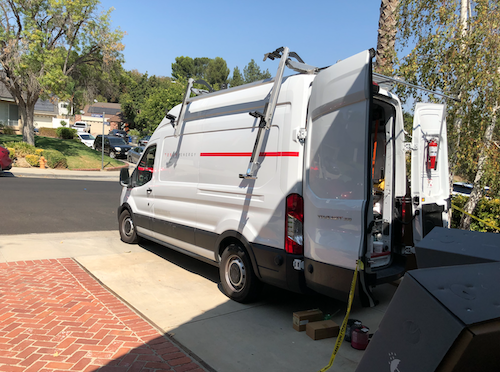
We are in the midst of a series of critical repairs at the Cox home. The pandemic forced us to postpone many of them, but slowly they are starting back up. This last week involved the removal and upgrade of our failing main electrical breaker box panel. Of course, that meant an extended power outage and the hourly “When will power be back on?” questions from my girls. I must say, we all gained a greater appreciation for our ancestors who navigated the 1800s with gas lights, candles and no air conditioning.
Speaking of appreciating our 21st century lifestyle, I love using Apple Pay! With the team of contractors working hard in the heat to get our power back on, I decided to make a run to our local grocery store to pick up some bottled water, Gatorade and snacks for them. As is my custom, I paid with my Apple watch. The customer behind me was shocked and struck up a conversation.
I grew up in the Midwest where you expected friendly conversations with random fellow human travelers all the time. However, that’s typically not how we do things in California. Here, everyone tends to be more focused on their own business, mostly without even making eye contact. But I find I still revert to my Midwest roots on occasion, much to the embarrassment of my kids, especially when there happens to be a cute baby in line with us. I just can’t help myself. Babies are irresistible. In any case, I happened to run into this concerned citizen in line with me at the grocery store who was seriously worried about my Apple watch. The conversation was really quite fun.
“Hey, aren’t you worried someone is going to steal all your information with that thing?” I responded, “Actually, it uses an encrypted token, not my info, to complete the transaction.”
“Like whatever, encrypted nothing, they got you! That’s dangerous! Can’t someone just decrypt it?” I really wanted to start drawing a diagram to explain how it worked, but I knew the rest of the customers in line were not interested in an extended lecture. I still switched into professor mode, “Sure, but just keep in mind, this isn’t my information directly, it is just a token identifier.”
“Man, you really are gullible.” I wasn’t making any progress. He shook his head but then proceeded to pull out his credit card in plain sight. I was able to clearly read his name, card number and expiration date printed on the front. No, I didn’t try to memorize it but was struck by the irony. He swiped his card with his in-clear-text magnetic stripe, also showing the CVV. Sigh. Yes, I guess I’m gullible.
I appreciate my friend’s paranoia, despite his negligence in protecting his own identity. No system is 100% secure. We know that. Several years ago, I had the privilege of teaching a cybersecurity class at USC where we explored the anatomy of an attack. One particular study was the 2013 Target breach. We examined all the points of vulnerability that existed in the system at that time. It began with a phishing scheme that equipped the attackers with a contractor’s credentials to log in to the energy management system for the stores. That led the attackers to a vulnerable Windows PC that just so happened to bridge the HVAC network with the global store network. That network was home to all the point of sale systems for all their stores. The card readers on those systems only accepted plain text magnetic stripe data. The hackers installed BlackPOS, a malware opensource package that intercepts track data. It began reading all of that data, sending it off to a server hosted in Russia. They managed to extract 40 million credit cards before they were discovered. A year later, the nearly exact same attack occurred at Home Depot, but for 56 million credit cards.
Vigilance is needed. Reliability engineering is not just about system performance or uptime, it is also about running secure systems. As we help design, build and run systems, this is a great reminder that we can all help safeguard our customers’ and company’s data. Have you found a vulnerability? Are you concerned about some missing measures or designs that should be modernized or addressed? If so, don’t wait, raise those issues. Speak up and act. You can make a difference. Let’s continue to help make our systems more secure for the good of the kingdom, our guests, businesses and fellow employees.
“I think it’s very important to have a feedback loop, where you’re constantly thinking about what you’ve done and how you could be doing it better. I think that’s the single best piece of advice: constantly think about how you could be doing things better and questioning yourself.” – Elon Musk
The Tesla Model 3 production line was too slow. Demand was high but delivery was low. The entire line was being delayed by one particular step in the battery production line. Specifically, it was a step where a fiberglass mat was added between the battery pack and the floor pan. Elon Musk talks about the focus that was suddenly placed on this choke point. In an interview he gave, he says he was basically living on that production line until they could get it fixed.
Automate, Accelerate, Optimize. To address the constraint in the system that was choking the throughput, Elon goes on to explain how they focused on the automation. To make the robot better, they adjusted the programming. They increased the speed from 20% to 100%, optimized the paths it would take, increased the torque, removed unnecessary motion and reduced the amount of product needed. Instead of spackling glue on the entire mat, they programmed it to deliver dabs of glue that were just enough to hold it in place, sandwiching it between the battery pack and floor. These all added up to some minor time savings.
After investing a lot of time into the efficiency improvements, it occurred to Elon that he didn’t even know the reason for these mats. He asked the battery safety team, “Are these mats for fire protection?” They answered, “No, they are for noise and vibration.” He then went to the noise vibration analysis team and asked them, “Are these mats for noise reduction?” They answered, “No, they are for fire safety.”
“I’m trapped in something like a Kafkaesque or Dilbert cartoon!” Elon discovered the mats had no reason to be included. After verifying with testing, they eliminated the unneeded parts that were choking the Model 3 production line. Production throughput increased.
How many times have you optimized a bit of code, a process or a system only to finally realize that the best optimization was to simply delete it? Before we take on some new work, a new project or even an improvement effort, ask yourself and others, “Do we even need this?” We all have limited time and resources. Some upfront investment in validating the real need can pay material dividends. Seek to eliminate waste. Instead of focusing on improving unneeded processes, let’s focus our efforts on things that deliver real value and outcomes.
Before automating, ask yourself if the time investment will deliver more value than we put in. Before accelerating, ask yourself if the haste will actually eliminate waste. And before improving something, ask yourself if we should just delete it instead. Challenge assumptions so we can ultimately deliver bold results that matter.
The famous Greek mathematician, physicist and astronomer, Archimedes had been given the task to verify that the king’s crown was made of pure gold. The king suspected the goldsmith had somehow cheated him, perhaps by mixing in a cheaper metal like silver. But he had no way of proving that so he asked Archimedes to figure it out. One day Archimedes was contemplating this problem while taking a bath. He happened to notice how the water was being displaced as he stepped into the full tub, spilling out all over the floor. He remembered that silver weighs less than gold by volume. It suddenly dawned on him that if he were to take the same amount of pure gold by weight as the crown, and put it into water, it should displace (spill) the same amount as the crown. Archimedes was so thrilled with this discovery that he immediately hopped out of the bath and ran to tell the king, exclaiming “Eureka!” which means, “I found it!”. In case you are curious, when Archimedes tested the crown, he discovered that it displaced more water than gold, indicating it was less dense (not pure gold). So, indeed the king had been cheated by the goldsmith. You can probably guess what happened to the goldsmith!
Learning is hard. There really isn’t a way around it. If you want to learn something, it’s going to take effort. I often use the excuse that the human brain is optimized to save energy. We build models and synaptic connections to do things “without conscious thinking.” We process huge amount of sensory data every day. We are faced with a plethora of problems we need to solve. It would be overwhelming if it wasn’t for these optimized unconscious neural pathways that allow us to sort, react and perform our tasks without much thought.
Learning builds more capability. At some point in our past, we learned something new and, Eureka! That learning was forged in our brains. It allowed us to perform our duties while we engage our higher brain functions for more important tasks like daydreaming, pondering the next season of Loki, or wondering what’s for dinner. Ok, so maybe those aren’t more important tasks, but you get the idea. By leveraging our learning, we expand our capacity to respond well to incoming tasks, difficult challenges, complex changes and even enjoyable exercises.
Learning builds on learning. I know that sounds a bit meta, but if you examine your own experience, you know that learning builds pathways to future learning. I remember the first time I learned to program a computer. It was hard! I was 12 years old and wanted to make my new computer display a Christmas tree for the holidays. Somewhere in the midst of typing in some code from a Dr. Dobbs Journal article, a Eureka moment hit and I understood the procedural flow that was happening. I had looked at more advanced programming techniques but they were out of reach for me, at least until I hit that Eureka moment. Suddenly that complexity was unlocked. That eventually led me down the path to discover microprocessor design, compiler construction and operating system development.
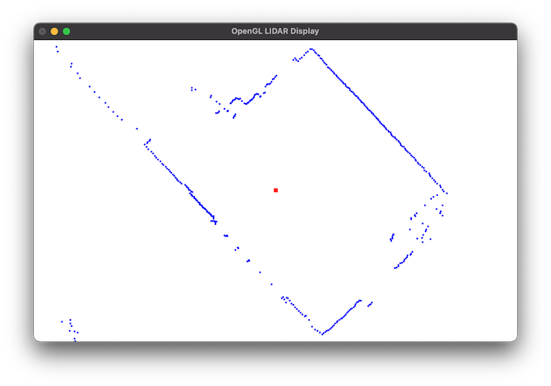
I recently purchased some dev kits, including a LIDAR kit. This past weekend I decided to learn how to use it to image my room as a stepping stone to my larger robotics navigation project. The funny thing about learning is that it often takes you on roads you didn’t expect to go. LIDARs are basically spinning measuring devices that use a laser to measure distance and send back angle and distance data. I wanted to visualize what the LIDAR was reading but the kit didn’t provide any imaging tools. So, I decided to learn OpenGL to render the output on my Mac. That became an exercise in itself but by the end of the weekend, I had a working project (see https://github.com/jasonacox/OpenGL-LIDAR-Display). It was challenging and frustrating at times. But as with any good learning effort, I had a Eureka moment that unlocked excitement and plans for future learning. I’m looking forward to the next phase!
What are you learning? When was the last time you had a Eureka moment? If you haven’t already, make plans this week to tackle something new to learn. Keep learning!
“The illiterate of the 21st century will not be those who cannot read and write but those who cannot learn, unlearn, and relearn.” – Alvin Toffler
As a kid, I was inspired by movies like TRON to explore computers. I caught the bug as soon as I saw how easily software could be used to shape reality and improve things. I spent 6 years skipping around between computer science, mathematics, physics, electrical and civil engineering. I even invested a year working toward a masters in divinity until I realized Koine Greek wasn’t a new computer language.
My dad was a civil engineer with crazy mad RPN calculator skills. He could crank out and tabulate thousands of calculations per day. But one day I wrote a bit of software and suddenly a week’s worth of tedious error prone work was done in minutes. He immediately hired me to “computerize” the rest of his business. With my educational background, I thought I was set… I could change the world (or at least my corner of it), one program at a time… but I still had a lot to learn. I soon discovered I didn’t know enough about statics and dynamics for the structural engineering work I needed to do. I also needed to dive deeper into 3D geometry and computer graphics for modeling complex systems. I went back to school.
There is a thought that education is just a box you need to check to begin your career. You may get certified, degreed or licensed and now you are done, right? Nope! Those are all great, but they are just visible footprints on the stairway of continual learning. Learning expands the mind and prepares us for more learning. Each step along the way reveals new vistas of knowledge to explore, new puzzles to solve and new mastery to obtain. We are forever on this learning adventure, growing and thriving on the food of knowledge, discovery and experimentation. Every new cognitive challenged unlocked is like an awakening. It is the physics of life. Each discovery expands who we are and carries us to a new level. We are alive and growing when we are learning.
Learning can be fun, but it isn’t easy. It takes work. It can be exhausting and even frustrating at times. Because of that, there is a temptation to become comfortable with our current state. We may find we can get by with what we already know, often for years without having to learn something new. But we aren’t growing. We become stale. Our capacity to move ourselves, our teams and our organization forward, withers. Like physical exercise, mental exercise is required to stay healthy, vibrant and alive. Just as we should plan to exercise our physical bodies to stay healthy, we should plan to exercise our minds as well.
What are you learning? May I suggest, if you aren’t learning anything new right now, pick something new and start learning it today? I know it isn’t easy, but embrace the constructive discomfort and expand your knowledge and skill. Tackle it. Imagine yourself thriving and growing. Don’t limit yourself. Set a goal to upgrade your knowledge every week. Study, grow and keep learning!