This project is to add a load cell to the filament spool holder of a Creality Ender 3 Pro 3D-printer to measure and display weight of spool. Using the tare function of the scale on an empty spool, the user can determine the amount of filament (in grams) remaining on a spool.
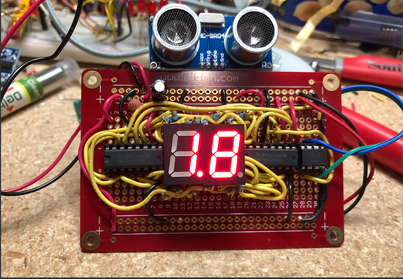
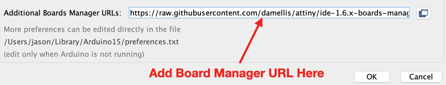
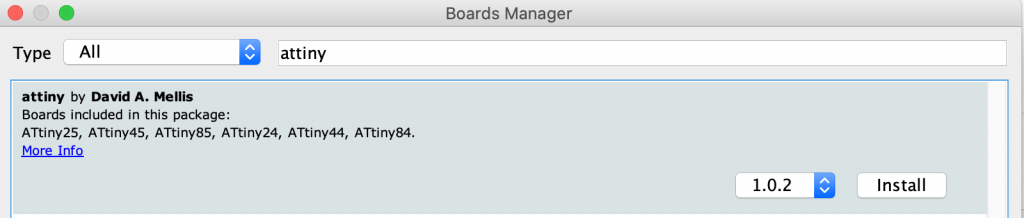
This project uses an Arduino or ATtiny85 microcontroller with the HX711 load cell module for weight measurement and a TM1637 4-digit LED display. Project GitHub Link
Components
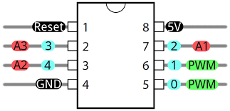
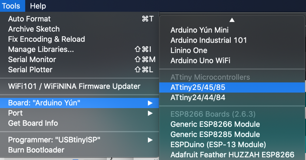
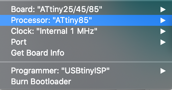
- ATiny85 Microcontroller (DigiKey)
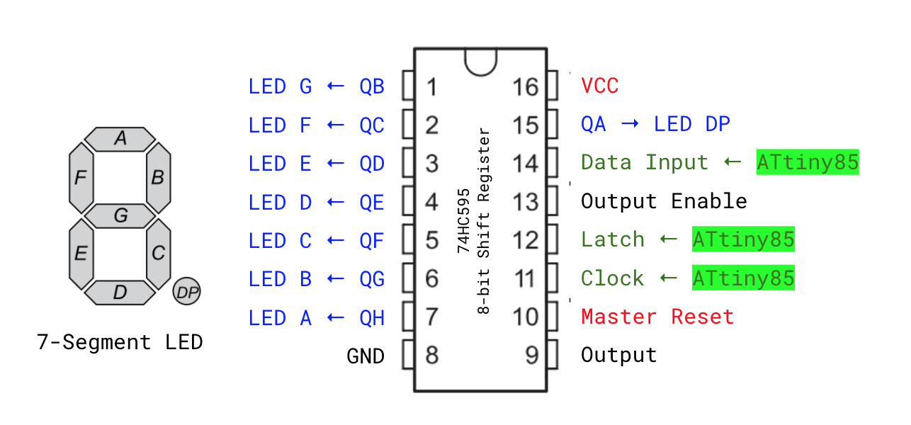
- TM1637 4 Digit Segment LED Display (Amazon)
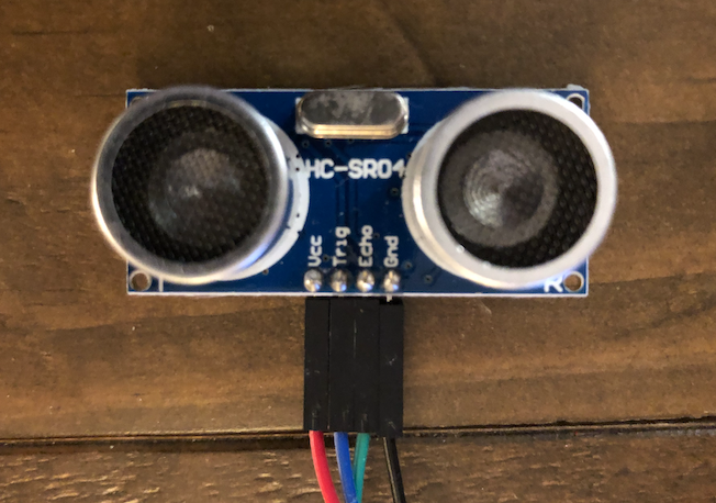
- Load Cell with HX711 Load Cell Amplifier (Amazon)
- 100uF Electrolytic Capacitor
- 5V Power Supply – Micro USB to DIP 5-Pin Pinboard (Amazon)
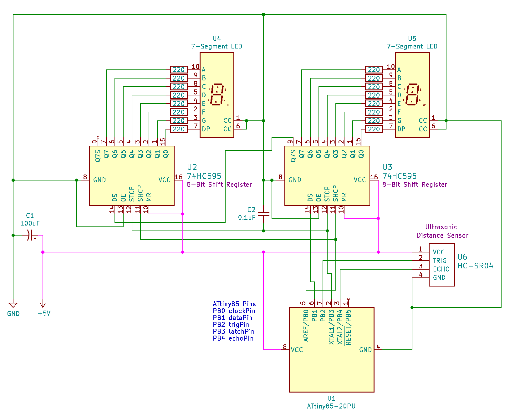
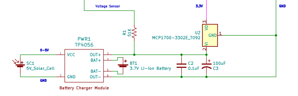
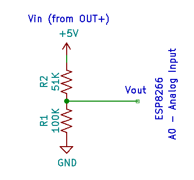
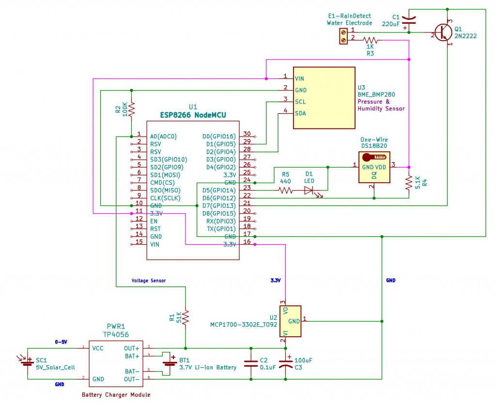
Schematic

How to Build
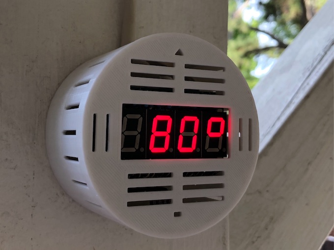
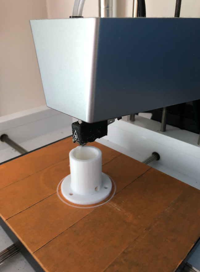
The filament scale mounts on top of the Ender 3 top rail where the filament spool is located. You will need to print the load cell mount and the LED display box. This is available on Thingiverse or Tinkercad. See example build pictures below.
Setup & Calibration
Download the Arduino code here: https://github.com/jasonacox/Ender3-Filament-Digital-Scale
This sketch requires that you calibrate the load cell. This involves the following steps:
- Run the sketch with DEBUG true (using a Arduino Uno or other microcontroller with serial)
- Record the “HX711 reading” values with NO load on the scale – this is your “
CAL_OFFSET“ - Use an trusted scale and weigh an object (grams or kg) – record this value as your “
KNOWN-VALUE“ - Place the object on the load cell and record the “HX711 reading” – this is “
CAL_VALUE“ - Compute the
CAL_RATIO= (CAL_VALUE–CAL_OFFSET) /KNOWN-VALUE - Edit the #defines in the code
    CAL_OFFSET  = -148550
    KNOWN_VALUE =  382.7186 g
    CAL_VALUE   = -107150
    CAL_RATIO   = (CAL_VALUE - CAL_OFFSET) / KNOWN_VALUE
    CAL_RATIO   = ((-107150) - (-148550 )) / (382.7186)
    CAL_RATIO   = 108.17
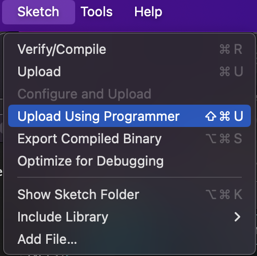
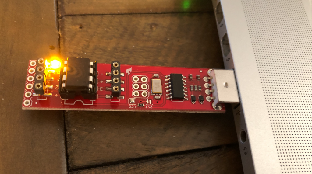
Programming Notes
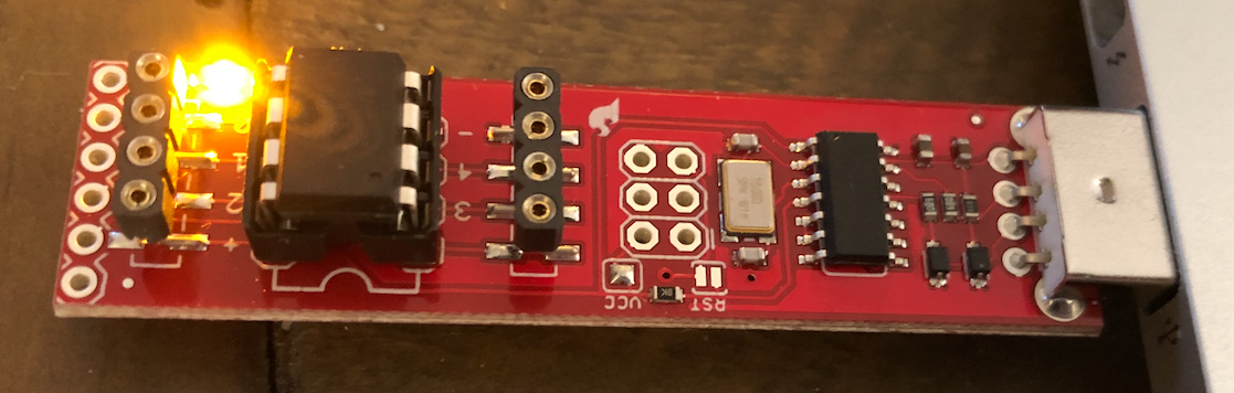
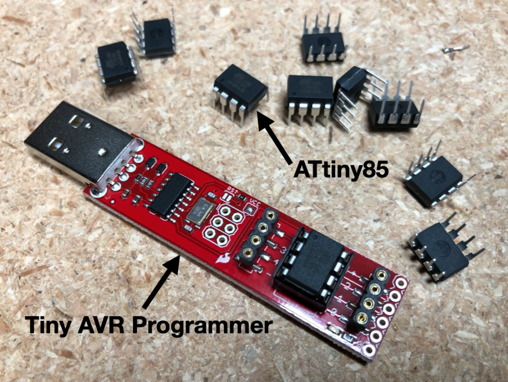
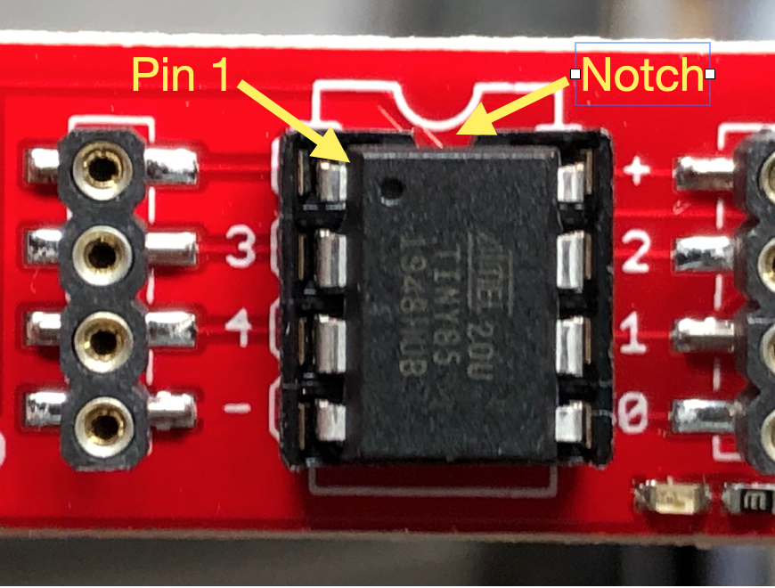
The TARE button uses PB0. If you use the Tiny AVR Programmer from Sparkfun it drives an LED on PB0 and once the sketch is uploaded, the ATTiny will read PB0 as LOW and assume you wish to TARE the scale. You will need to remove the the chip from the programmer after uploading to get it to work correctly in the circuit.
Tare Function
On start the circuit will read the last TARE value from EEPROM and display the the current weight. Press and hold the TARE button and the current weight value will be recorded in EEPROM and subtracted from the current reading to “Zero” out the scale.
Assembly
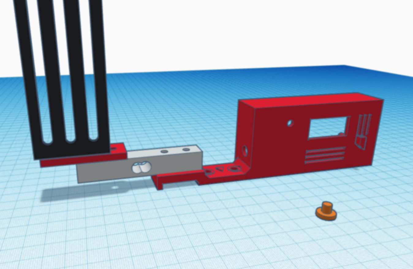
The 3D model for the case and load cell mount is on Tinkercad and available for download on Thingiverse. The case is open-back for simplicity and it has mounting holes that use the existing spool bolts and fasteners.
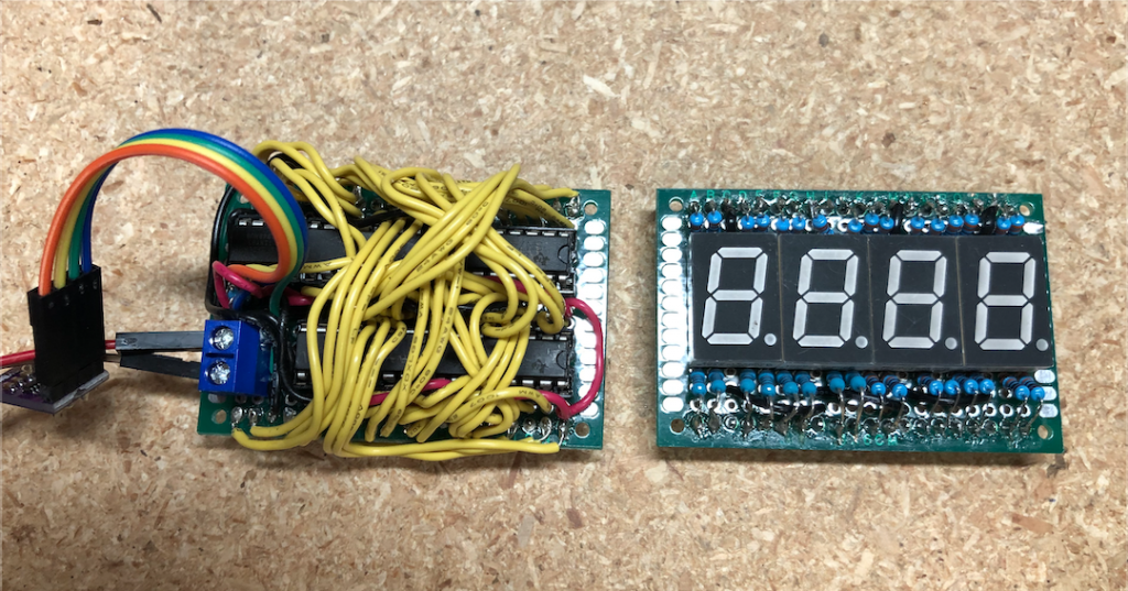
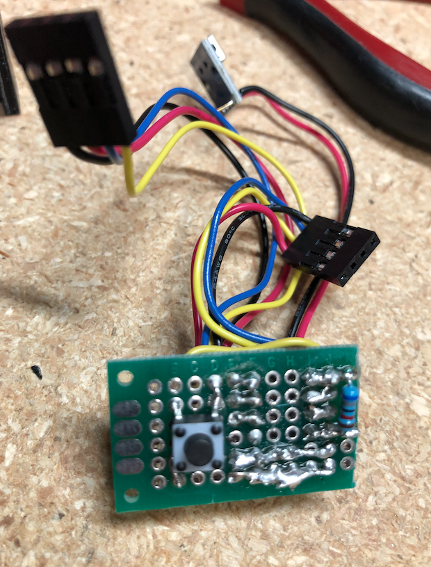
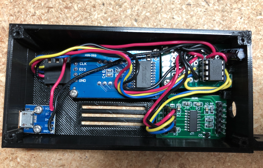
I used a small 20mm wide project circuit board to mount the ATtiny85 socket, resistor, electrolytic capacitor and microswitch. The microswitch is located on the bottom and will face the hole on the front of case. A circular 3D printed button will fit in the hole and press against the microswitch to activate the TARE function.
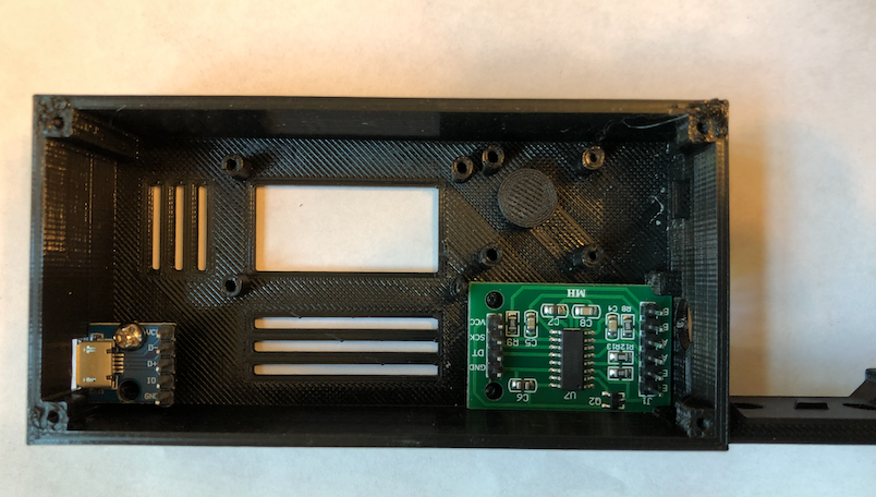
The case is designed to hold a USB plugin board, the TM1637 display, the controller board and the HX711 load cell module. The HX711 slides in with a hole on the side to feed the load cell wires.
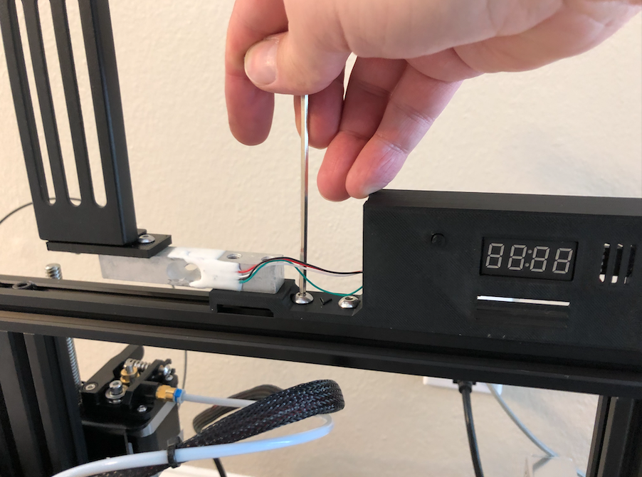
You will need M5 bolts to mount the load cell onto the 3D printed case bracket (see pictures below) with bolts going up into the threaded load cell holes. The filament spool holder that came with the Ender 3 Pro will attach to the “load” end of the load cell (the end marked with the down arrow and max weight). A 3D printed shim adapter will go between the filament holder and the load cell. An M4 bolt will go down and tighten into the load cell. The other M4 bolt will need a M4 nut under the shim.
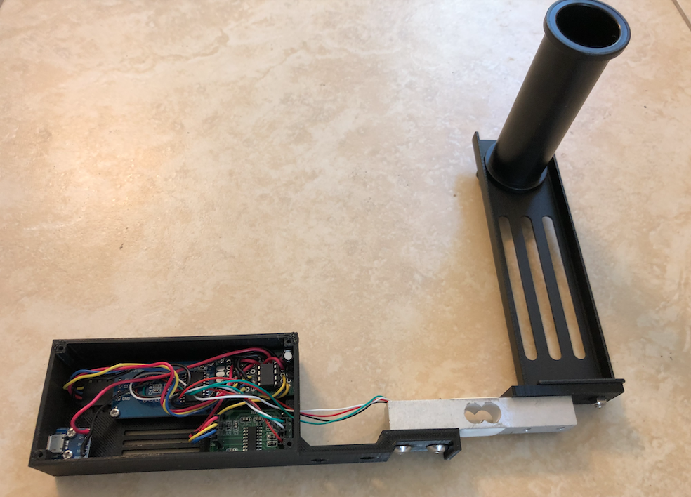
Attach the scale and filament holder back on to the top of the Ender 3 Pro using the two M5 bolts and M5 T-nuts that came with the printer.
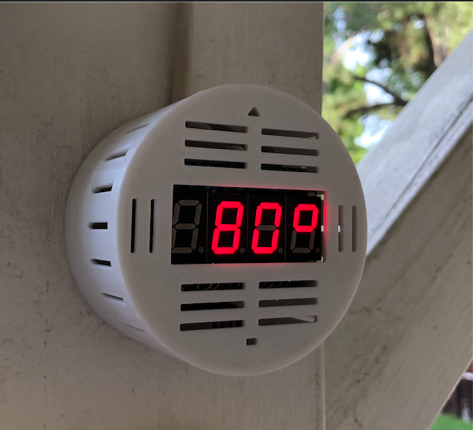
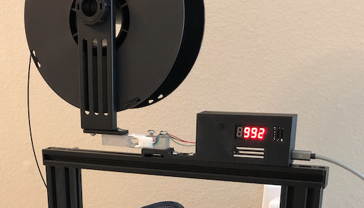
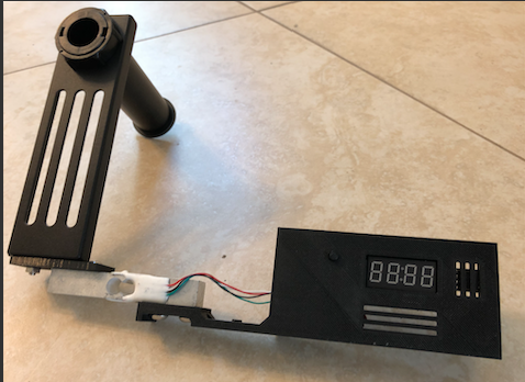
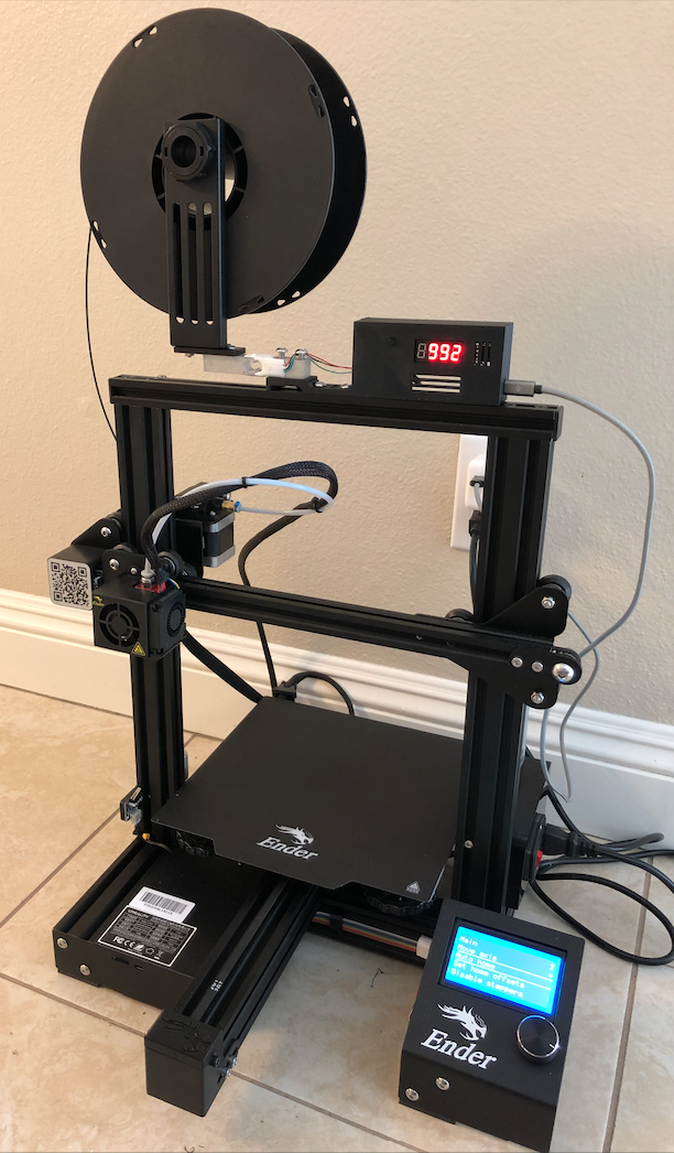
Plug in the scale and put an empty filament spool on the holder. Press the TARE button to zero out the weight (it records this TARE value in EEPROM memory so it remembers it on power cycle – you shouldn’t have to use TARE again). Now replace the empty spool with one with filament. It will now show you the estimated amount of filament remaining. it has been surprising accurate for my project. Notice the example below shows a slightly used 1kg spool is reading 992 grams.
Optional Roller Addition
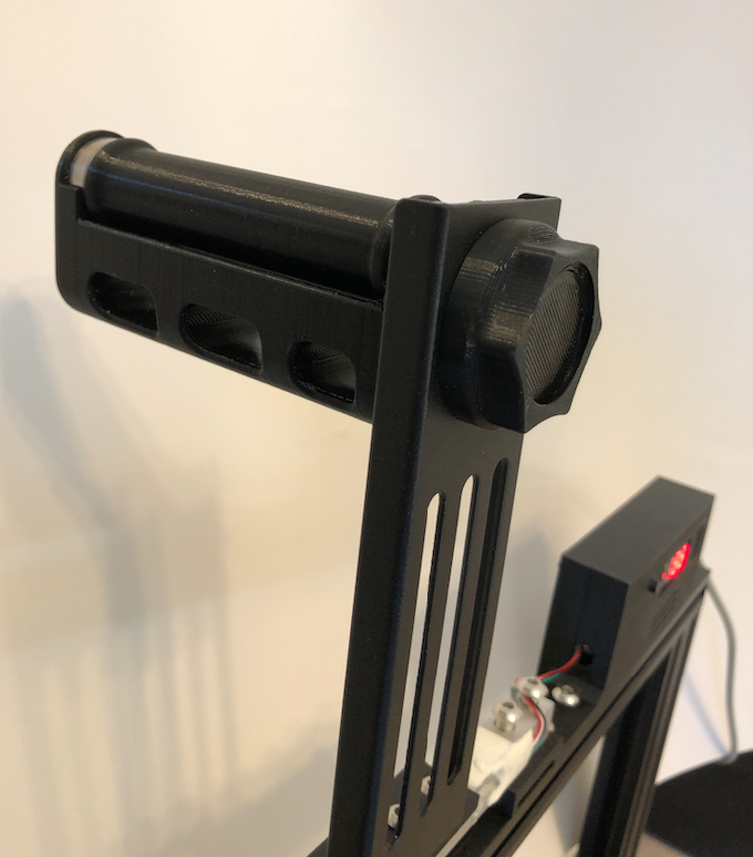
I immediately noticed that when printing, as the extruder stepper pulls the filament, the weight will change, reflecting the dynamic force of the pull and the sliding friction resistance of the static spool holder rod.
I decided to addd a real roller to the spool holder so I printed this model that uses two bearings to remove friction: https://www.thingiverse.com/thing:3209211
References
- Project Code: https://github.com/jasonacox/Ender3-Filament-Digital-Scale
- TM1637TinyDisplay
- Library for HX711 https://github.com/bogde/HX711
- 3D Models: (1): https://www.thingiverse.com/thing:4545434 (2): https://www.thingiverse.com/thing:3209211
- HX711 Load Cell Amplifier, Weighing Scale Design https://circuits4you.com/2016/11/25/hx711-arduino-load-cell/