Who left the garage door open?
We have a full house with a lot of activity and visitors. There have been several times when the garage door is left open for extended periods of time. While our Christmas decorations and paint supplies may not be a treasure most would be thieves would desire, it is still not the most comforting thing to think about leaving the garage open for all passerby to see. I often thought it would be great to have a way to notify whoever is in the house that the garage is open.
Phase 1 – LED Indicator
I decided that my first step would be to design a way to detect “door open” by providing a simple indicator light. I explored a few optical ways to do this (light beam, camera, reflectors) but quickly pivoted my approach when I found some unused microswitches.

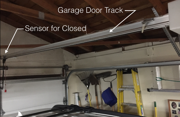
I found a good place to detect “closed” on the main track. I thought about piggybacking on the garage opener sensors but dismissed that as I didn’t want to risk an undesirable interaction with the opener and more importantly, I wanted to have the detection work even if power to the opener was interrupted.
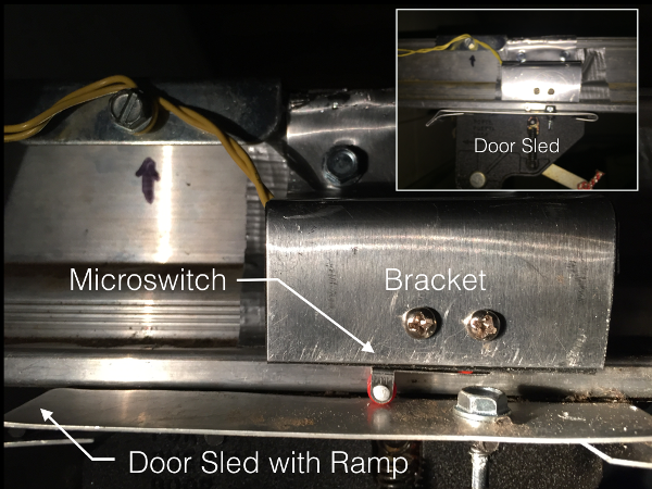
This required that I build a bracket to mount the switch to and a ramp plate to compress the switch when the door was in the down position.
I used an aluminum sheet, cut with sheet metal snips, bent 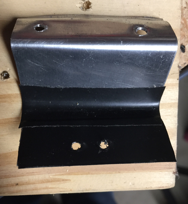 and drilled holes to mount the microswitch and eventually attach it to the garage door track. It took a few tries to get the right fit and right placement of the micro switch.
My first attempt destroyed the microswitch after a few uses. The garage door track sled has a straight edge that collides with the microswitch roller. It created too much force on the small roller and eventually popped it loose. To help with that, I 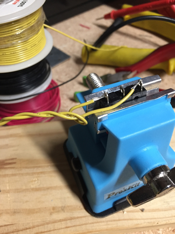 added an aluminum ramp to the sled so that the microswitch roller would gently rise as the sled entered the “closed” position.
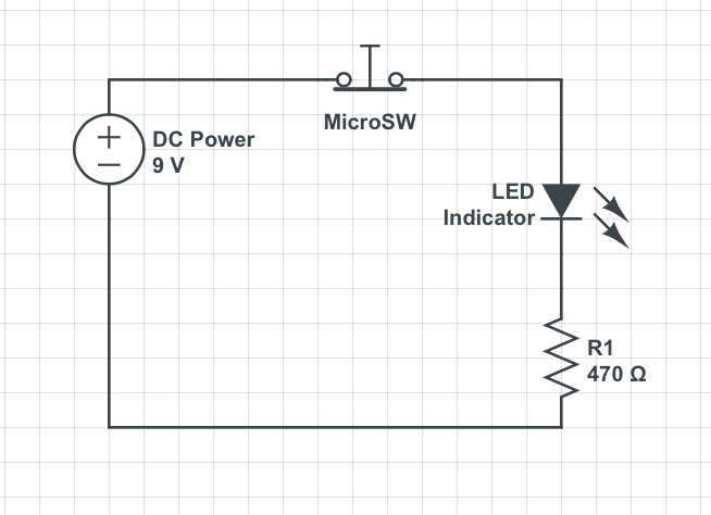
I decided to make the “door open” state be the closed circuit condition so that phase 1 of the project could start as a simple LED circuit indicator.
I attached the switch and drilled some pilot holes and mounted the bracket to the garage door track right above the sled when the door is in the closed position.
I added a 9V battery, a 470 ohm resister and a red LED to the circuit. To complete this phase, I ran the wire from the garage to our entry hall and mounted an LED and housing above the HVAC controls. Now we can all see the brilliant red LED glowing when the garage door is open. That covers some of our use cases but I also want a more proactive notification. Now on to phase 2…
Phase 2 – Raspberry Pi – Home Automation Sentry
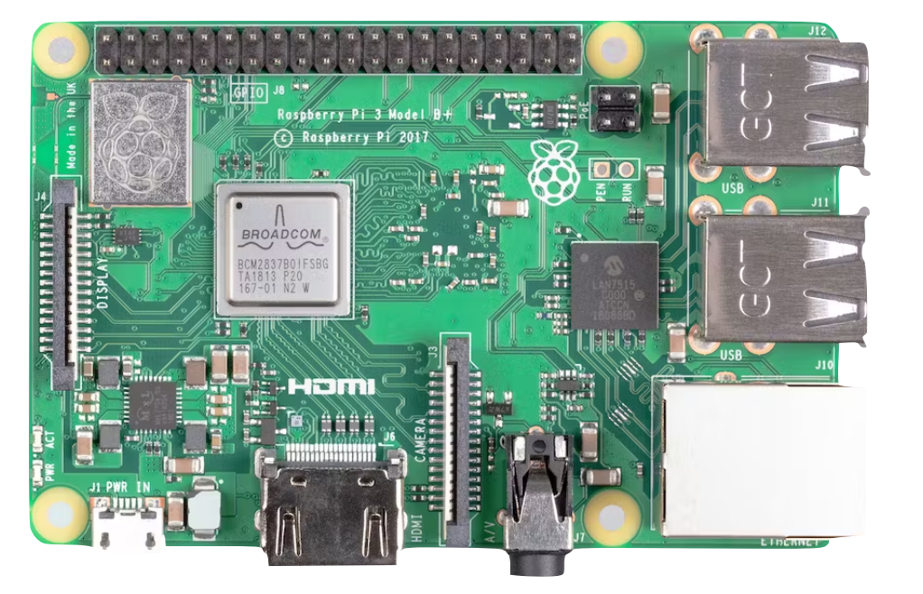
Now that I have a working “door closed” sensor and indicator, I am ready to add the proactive home automation component, specifically the Raspberry Pi (RPI). It just so happens that I have a spare RPI Model 3 that needed a project, and I wanted to experiment with AWS IoT services.
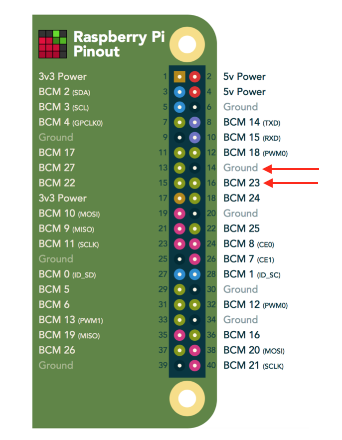
I used the RPI to detect the state of the switch. To do that, I will need to wire the circuit into the RPI’sGPIO headers. I decided to use GPIO Pin 23 and the adjacent ground (GND) pin.
Here is the code that is used to detect the closed circuit (indicating an open door):
#!/usr/bin/python

##
## Garage Door Sentry - RPI script to monitor door
##

## load libraries
import RPi.GPIO as io
import time

print "Garage Door Sentry\n\n"

## set GPIO mode to BCM - allows us to use GPIO number instead of pin number
io.setmode(io.BCM)

## set GPIO pin to use

door_pin = 23
print "Sentry Activated - Watching: GPIO 23"

## use the built-in "pull-up" resistor
io.setup(door_pin, io.IN, pull_up_down=io.PUD_UP)  # activate input

## States for door: 0=closed, 1=open, 2=init
door=2
## infinite loop
while True:
    ## if switch is open
    if (io.input(door_pin)==True and door!=0):
        door=0
        print "Door closed"
        # do some action
    ## if switch is closed
    if (io.input(door_pin)==False and door!=1):
        door=1
        print "Door open"
        # do some action
    time.sleep(1) # 1 second wait
The next step was to connect to AWS IoT to record this sensor data and send alert messages to my phone.
The following will help you set up your Raspbery Pi as a platform to install the SentryPi scripts.
Required:
- Raspberry Pi – B+, 2 or 3
- Wifi Dongle or Network Cable configured
- SD card (Recommend: 16GB or larger)
- AWS Account (IoT, DynamoDB)
Read the details on this GitHub Project: https://github.com/jasonacox/SentryPi
The project describes how I added these additional features:
- Sentry Alert – Send a text message to contacts when an alert condition is reached.
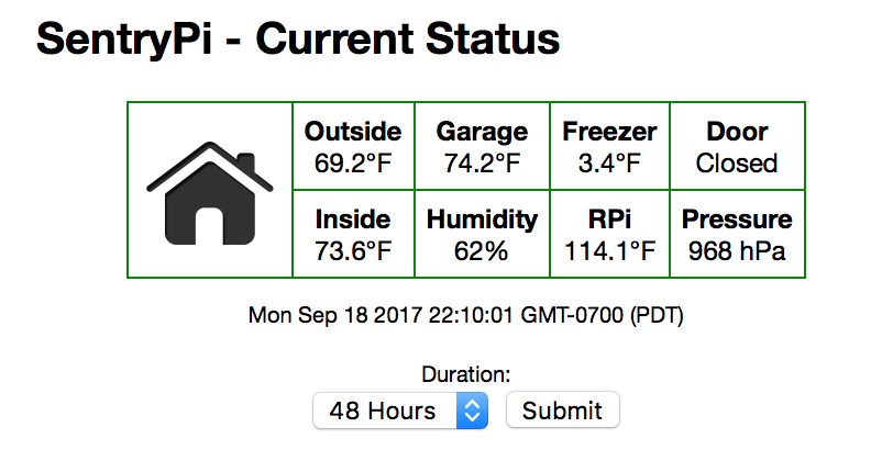
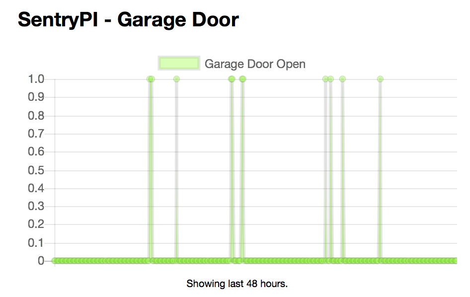
- Dashboard – Provide an automation dashboard for realtime status.
- Other Sensor Data:
- Temperature Sensors
- Barometric Pressure Sensor
- Humidity Sensor
- Motion Sensor
To set up a web based dashboard, I decide to use static HTML, CSS and JS (jQuery, Chart.js and the AWS JavaScript SDK) so it can be hosted on a simple S3 bucket, a web server, or the RPi itself. See here for the code.